Hardware
Table of contents
Wire harness
In the configuration with the Jetson Orin, the 12V is directly fed to the D131 carrier, interruptible with a power switch.
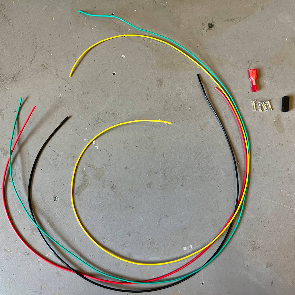
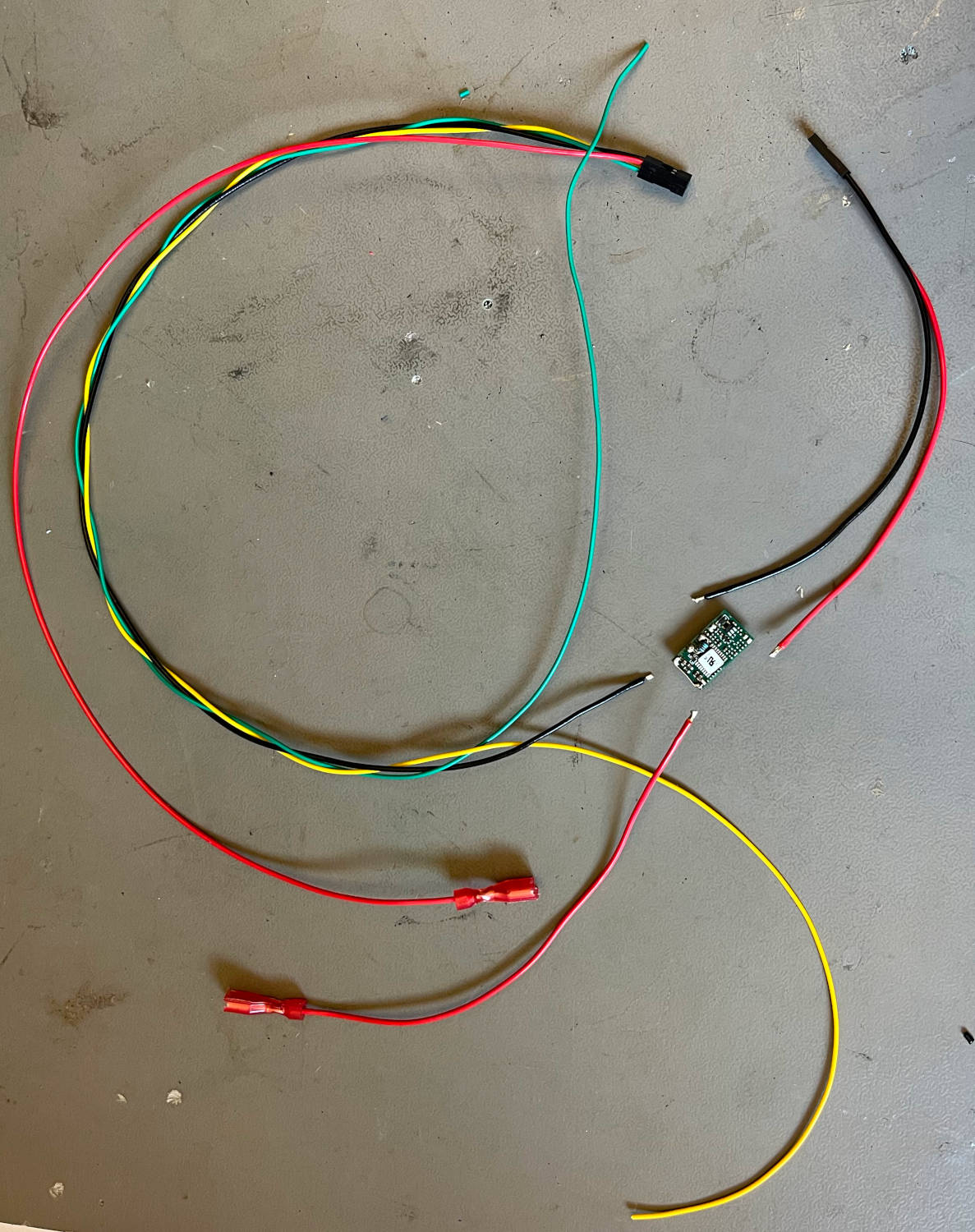
Overview of the wires and components used in the UI assembly.
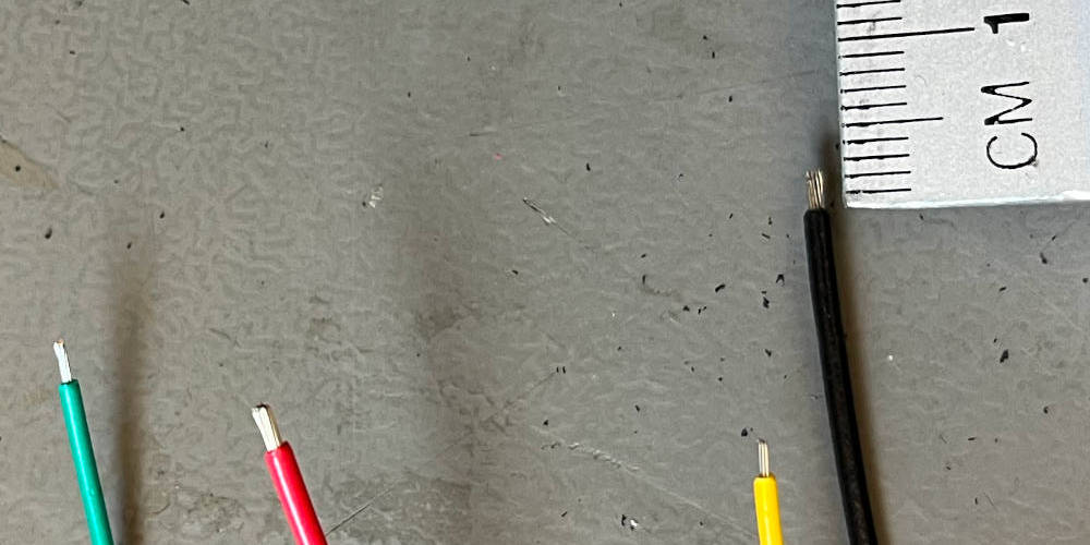
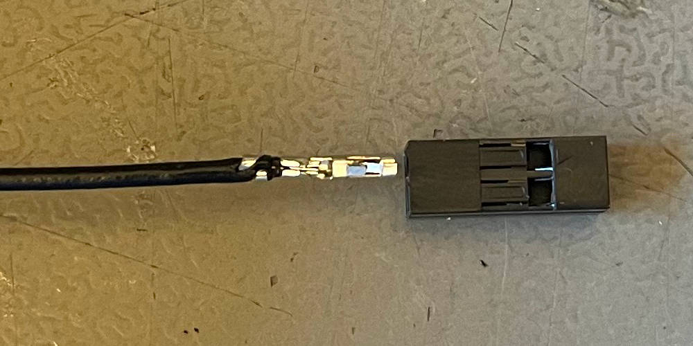
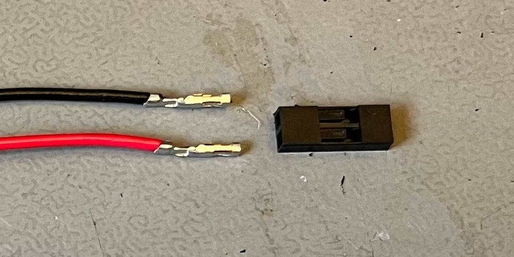
Remove the cable isolation on one end to prepare for crimping.
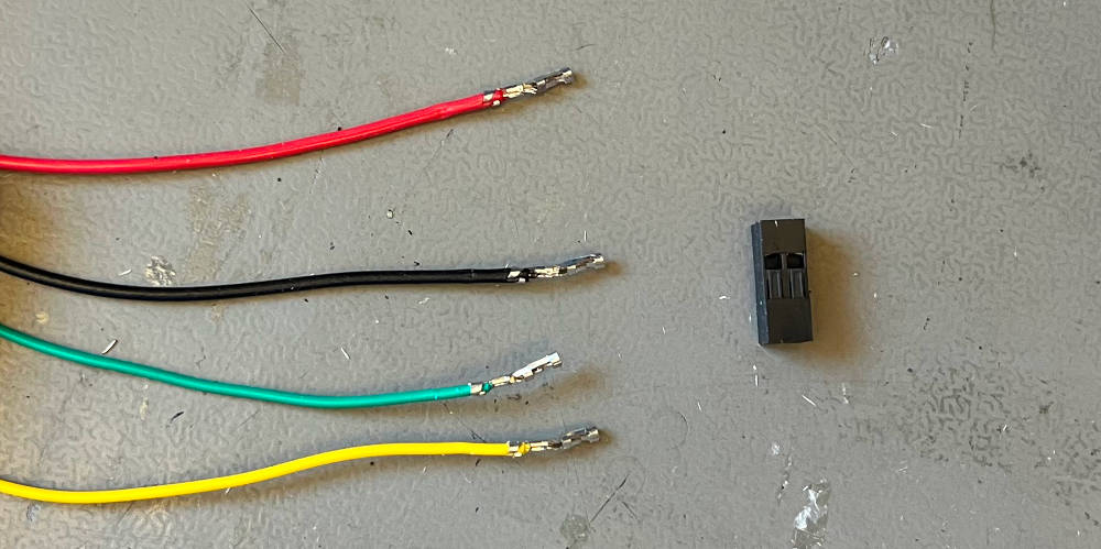
Crimp the four cables according.
Insert the cables into the 2x2 housing. Start with the black cable at pin 1, indicated by the arrow. It is important to inser the cable with the correct orientation.
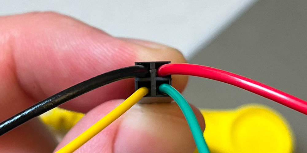
Insert the remaining cables.
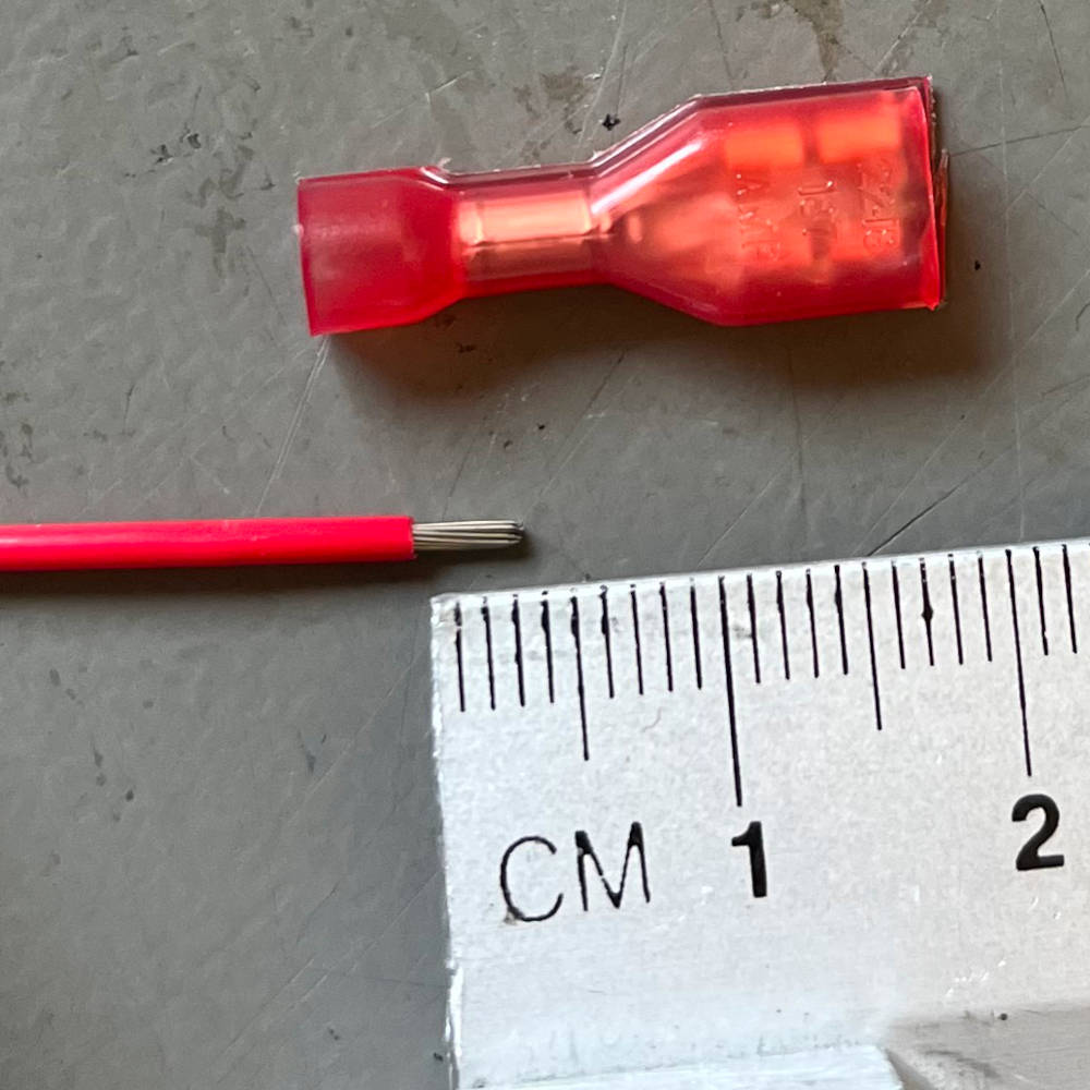
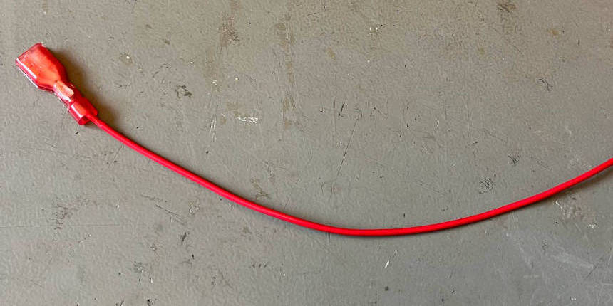
Isolate the end of the red cable and crimp the switch contact.
Weave the black, yellow and green cable.
Take the two short black and red cables. Isolate and crimp both and insert them into the 2x1 housing.
Take the short red cable and crimp one end to the power switch connector.
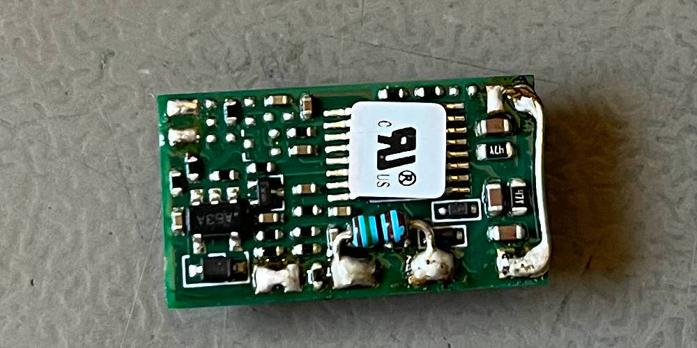
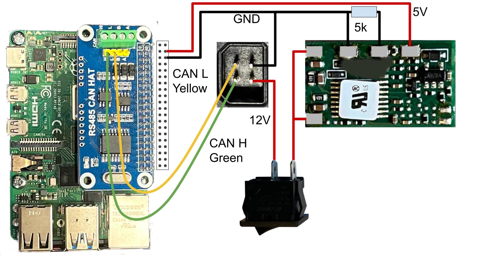
Take the DC/DC converter and connect the bridge on the right right, as well as the resistor, as indicated in the picture.
Arrange all components as indicated.
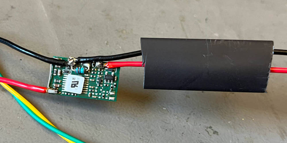
Cut all wires to the appropriate length and isolate the endings. Solder the 12V lines coming in from the RoboMaster to the left side of the DC/DC converter, and the 5V lines going out to the right side. Apply a large piece of heat shrink tubing to the converter.
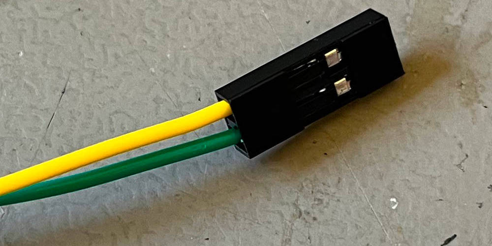
Cut the yellow and green cable to a similar length, crimp the endings and insert them into the 2x1 housing.
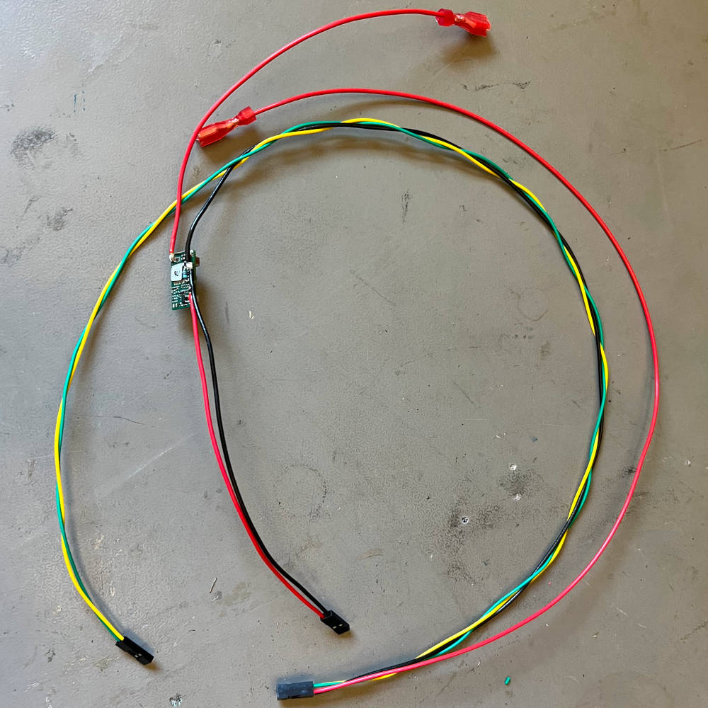
This is what the harness looks like after soldering and connecting all wires.
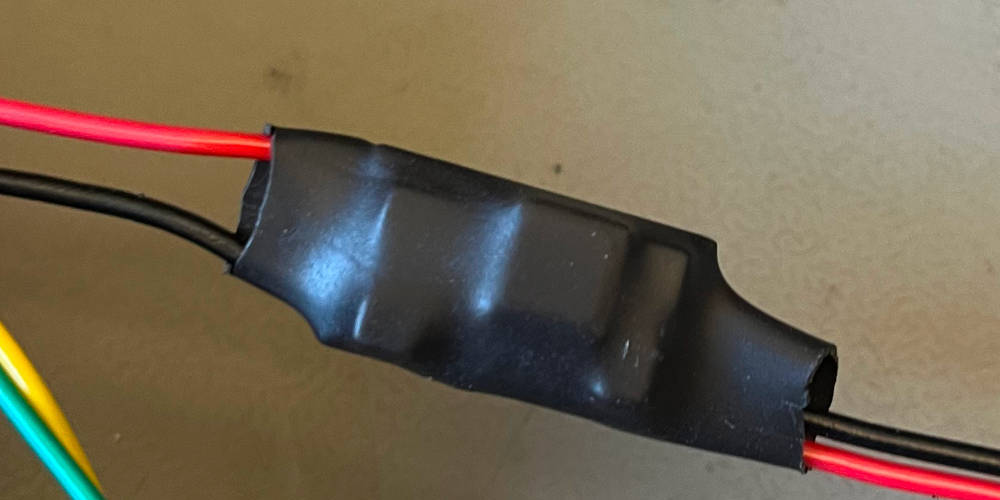
Pull the heat shrink over the DC/DC converter and apply heat with a hot air gun.
Robot
Robot base common, UI
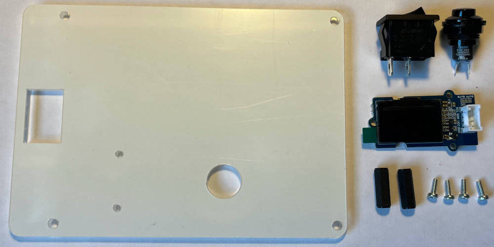
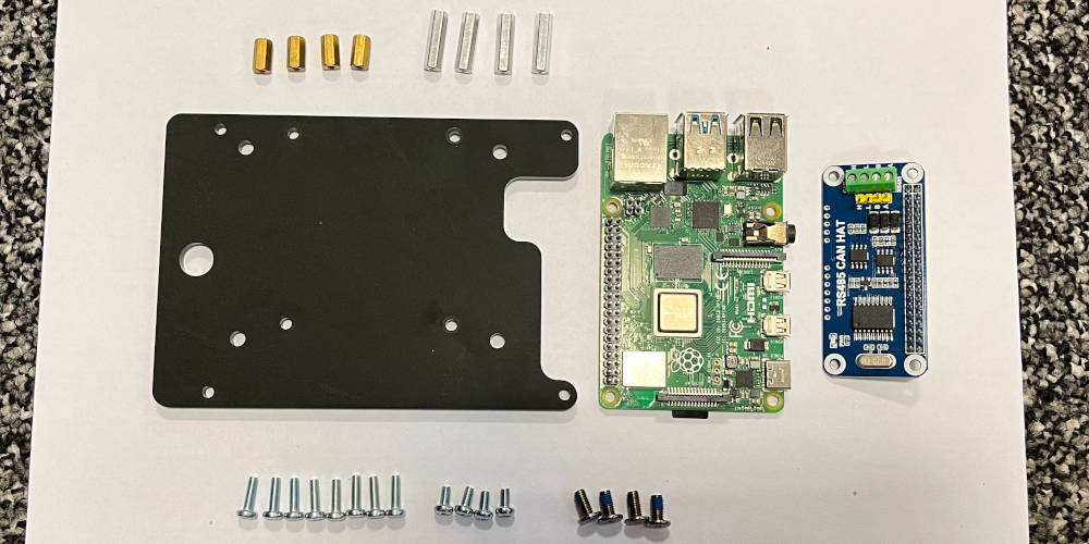
Overview of components needed.
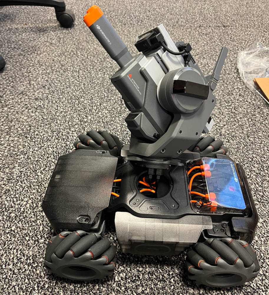
Unscrew the four turret screws and set them aside.
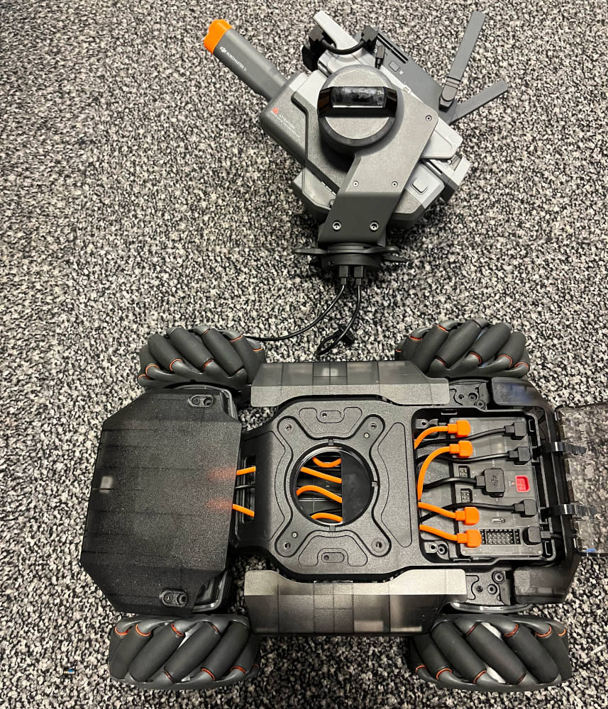
Remove the turret by disconnecting its two cables from the controller.
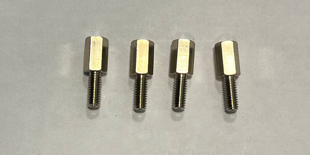
Screw in the four standoffs in place of the turret.
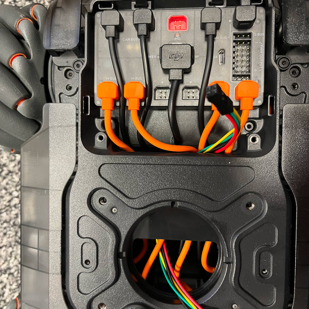
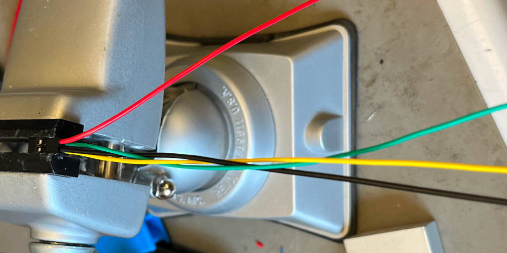
Take the assembled wire harness and thread through the 2x2 connector through the base to the controller.
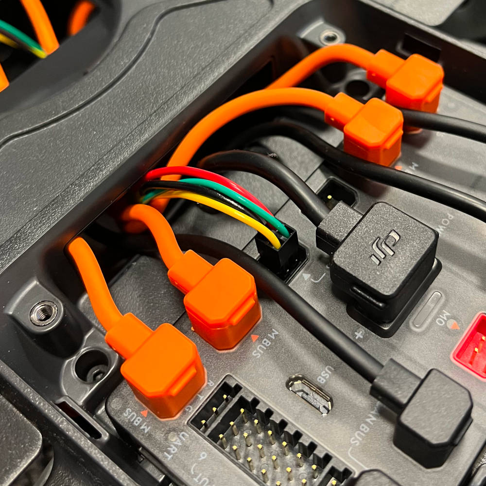
Connect the wires to the controller. It is essential that the wire is plugged in correctly, with black and red facing towards the center of the robot. It is possible to plug in the wires four ways, and plugging them in wrong will break the computer.
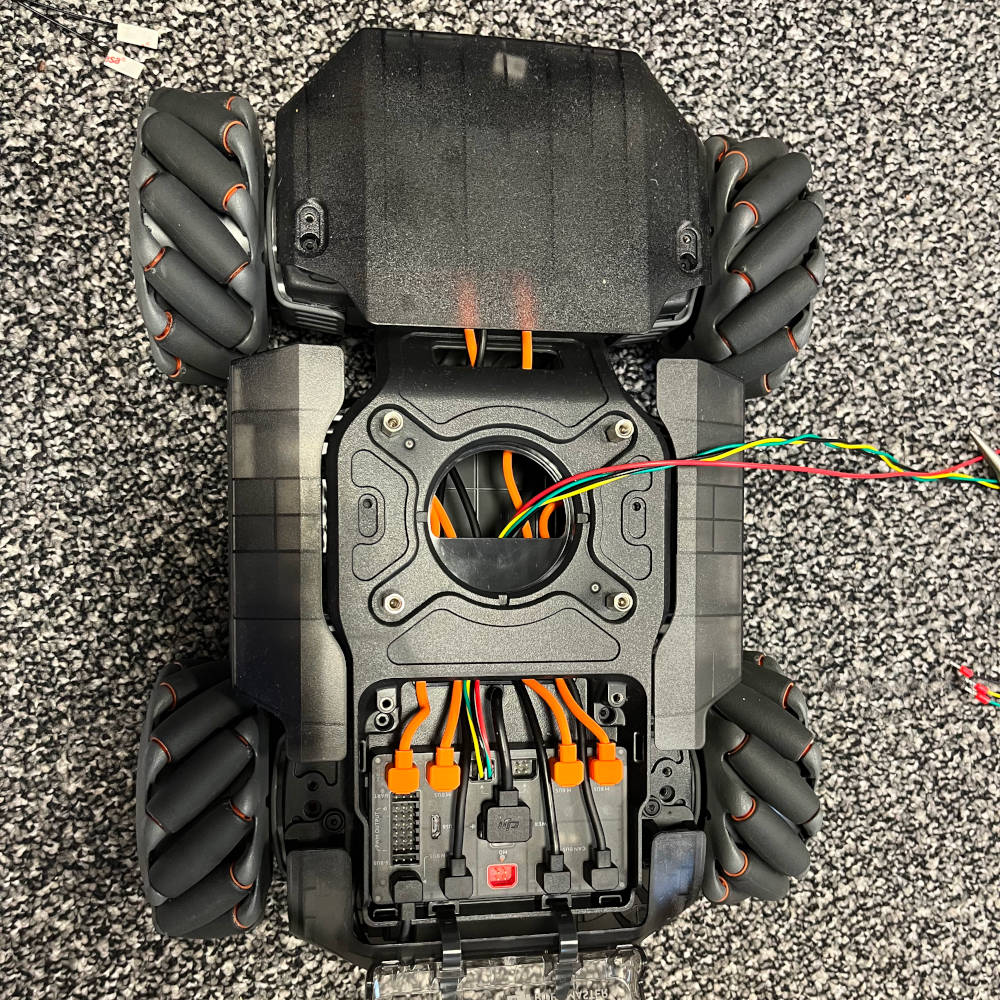
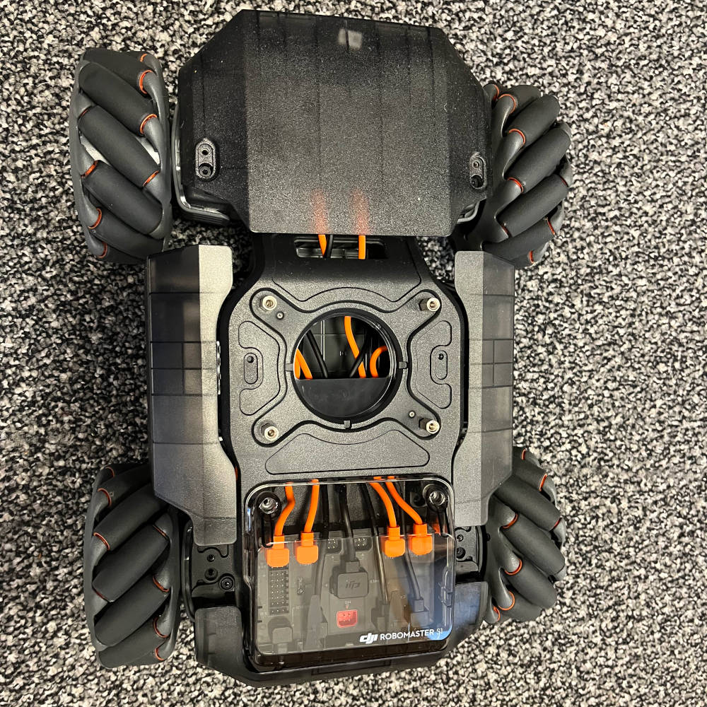
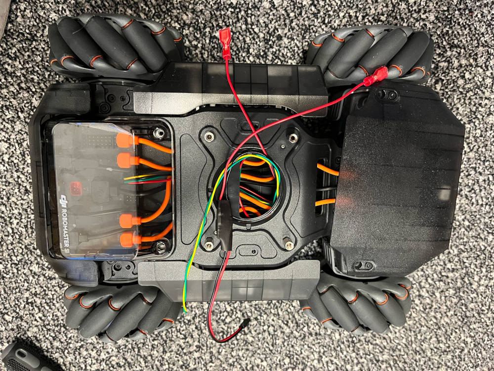
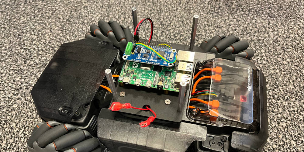
Overview of the base, with four standoffs and wire harness mounted.

Find the cable supplied with the display unit.
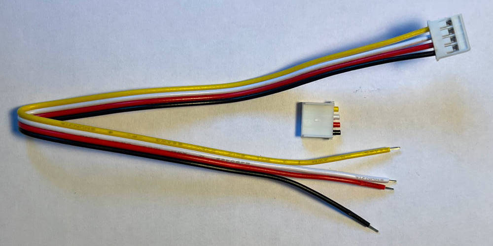
Cut off one end of the connector and prepare the cut off end of the cable for crimping.
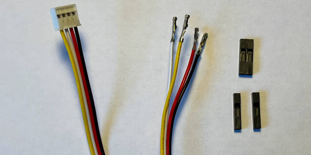
Crimp all four wires and find the crimp housing (1x 2, 2x 1).
Connect the white and yellow cable to the 2x housing, and the black and red cable to the 1x housing.
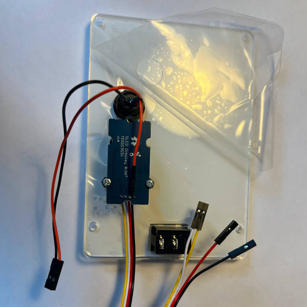
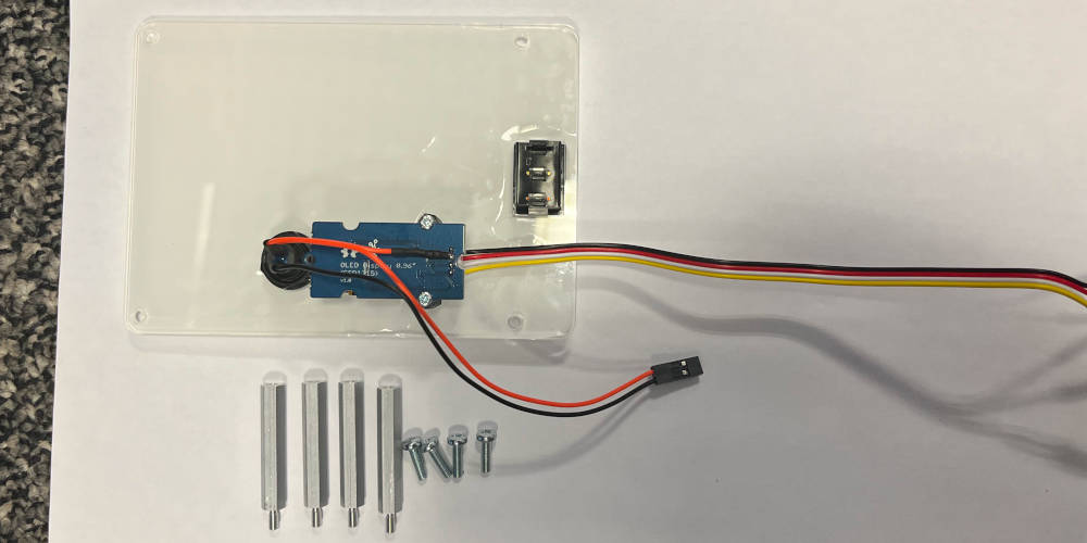
Overview of the parts used in the UI assembly.
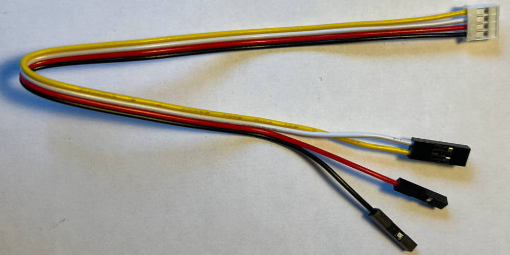
Overview of the wires used in the UI assembly.
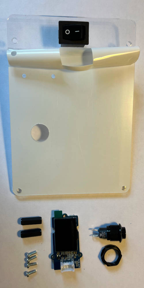
Align the front plate so that the rectangular hole is on the left, and the circular hole is on the bottom. Align the switch so that the off-position is on the bottom. Remove protective screen around the switch if necessary. Press the switch into the rectangular hole. Re-attach protective screen on top of the switch (optional).
Turn the front plate on its back. Remove protective screen around the switch if necessary. Unscrew the nut from the button if not already done, and insert it through the front. Then screw the nut back on.
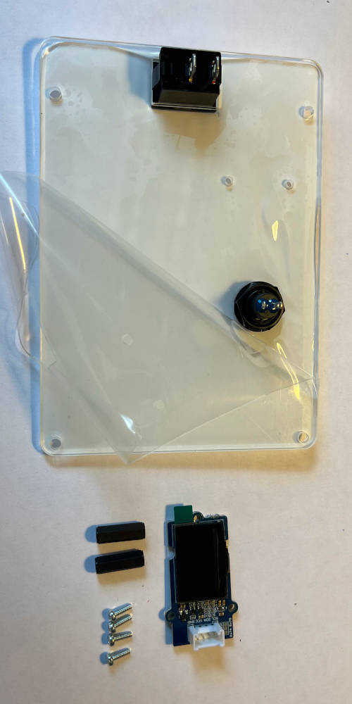
Take two screws and two distance bolts. Remove protective screen around the screw holes if necessary. Mount the distance bolts as indicated with two screws.
Attach the display cable to the display. Mount the display to the front plate on the standoffs.
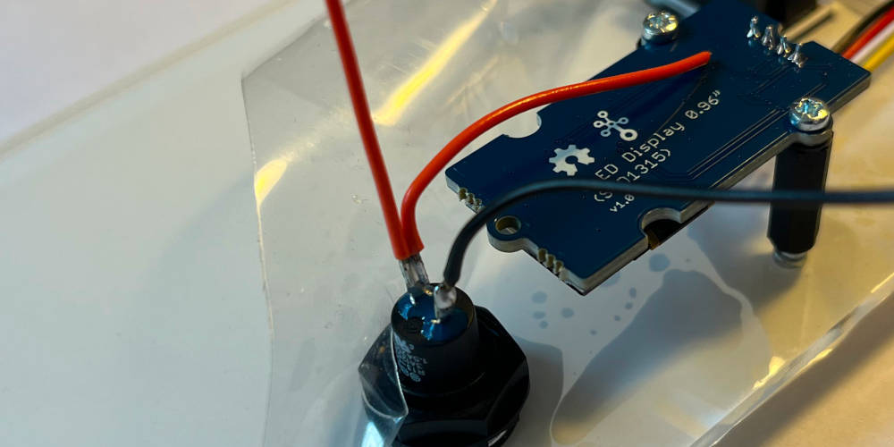
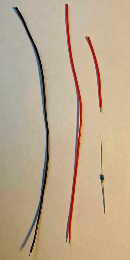
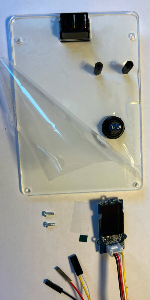
Take the wires and remove isolation from one side for soldering. Solder two colored wires to the top pin of the button so that the shorter wire is facing the display, and the longer wire facing upwards. Solder the black wire to the bottom pin.
Take the pullup and cut one end to about 0.5cm length. Solder it to the second pin of the display (counted from top, pin corresponding to the red wire on the display). Cut the shorter cable of the button facing the display so that there is some overlap with the resistor, remove isolation and apply solder it.
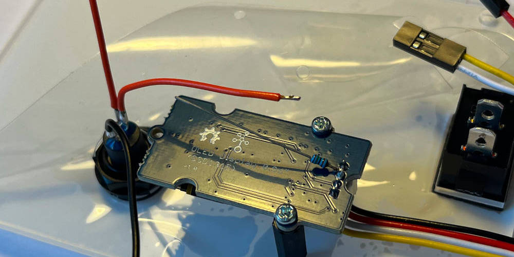
Cut three pieces of heat shrink and put them on both wires of the button and the resistor. Cut the resistor to the appropriate length so that the cable can be soldered on it.
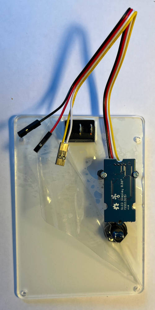
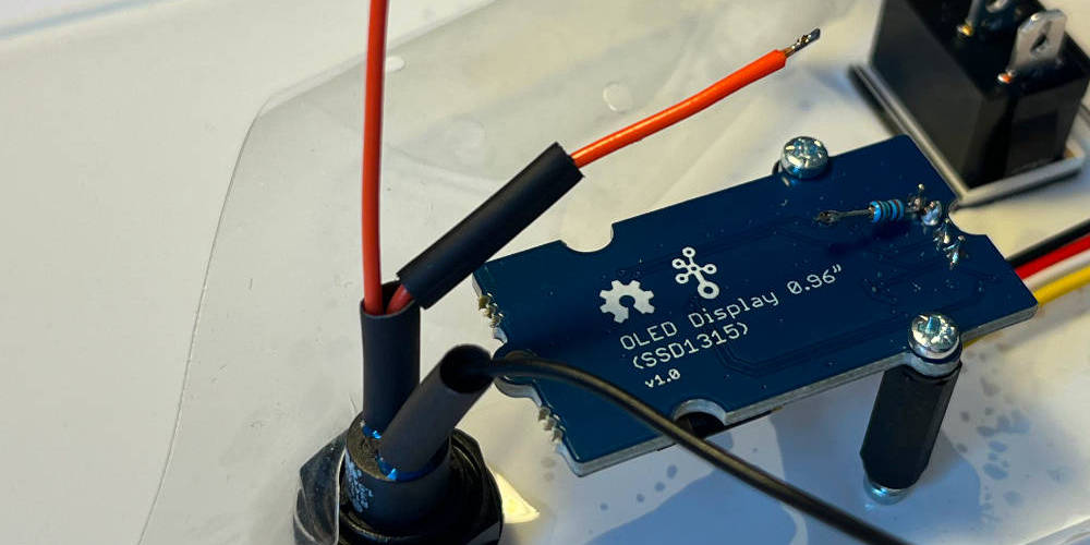
Apply heated air to all heat shrinks. Cut the wires of the button to a similar length and crimp the endings. Prepare a 2x housing.
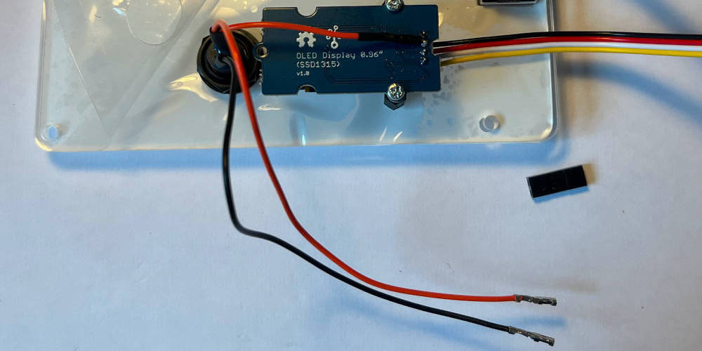
Insert the button wires into the housing.
Start by laying out the wire harness. The two red wires should be together between the two topmost distance bolts. The power supplt and CAN connectors should both be between the opposite distance bolts. If the cables are too long, tuck them into the hole of the base unit as appropriate.
Overview of components used in the base assembly.
Mount the four 17mm and four 10mm bolts to the base plate, as indicated, using M3 screws to fixate them.
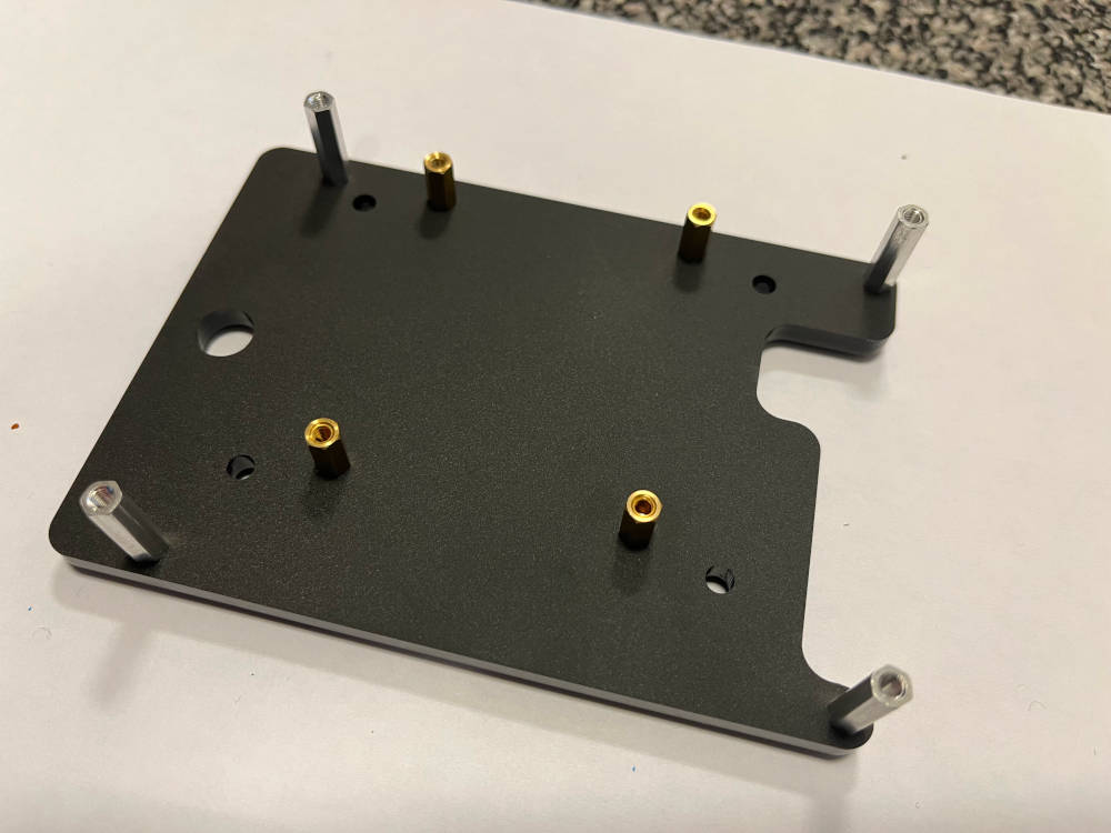
The four shorter bolts serve mounting the Raspberry Pi, the four longer bolts serve mounting the UI unit.
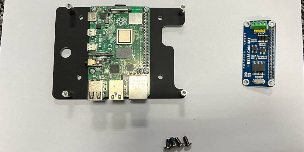
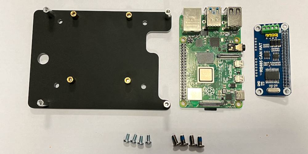
Mount the Raspberry Pi on top of the four 10mm bolts using M3 screws. The holes of the Raspberry Pi might have to be drilled out to fit the M3 screws.
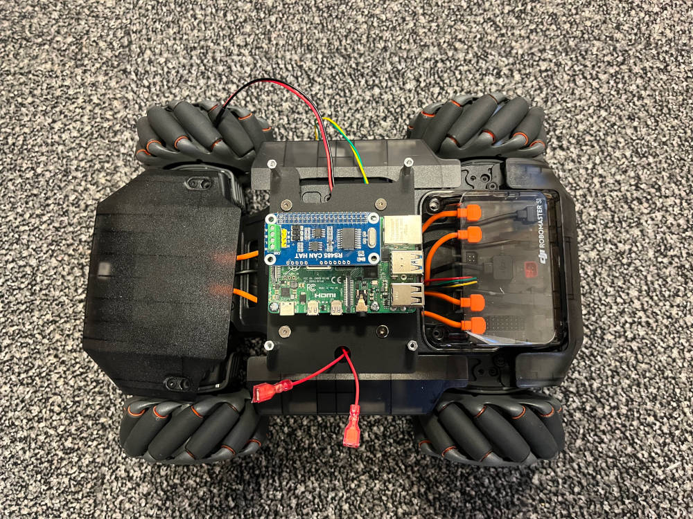
Use the four M4 screws originally used to mount the turret on the RoboMaster to fixate the base plate. Make sure the cables are aligned as indicated. Attach the CAN hat.
To recall, this is the wiring schema for the Raspberry Pi.
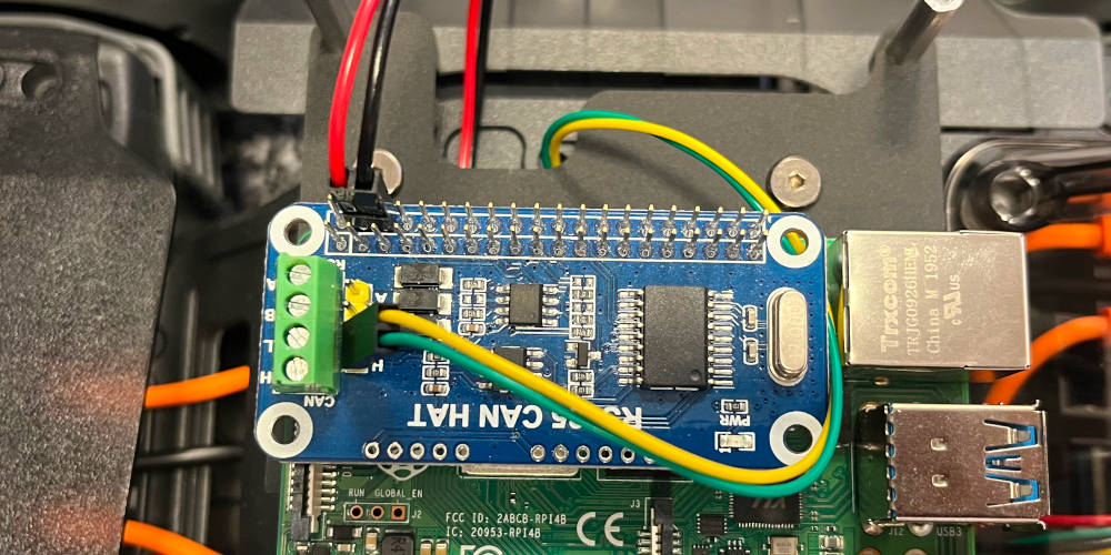
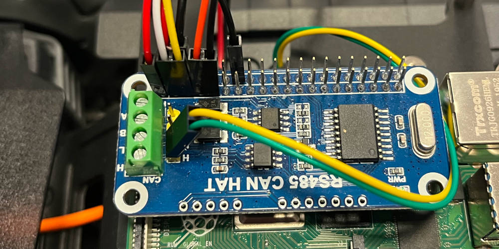
Attach the power supply line and CAN line to the CAN hat as indicated.
Overview of components used in the UI unit assembly.
Attach the four 35mm distance bolts to the distance bolts on the base.
Connect all UI unit wires as indicated.
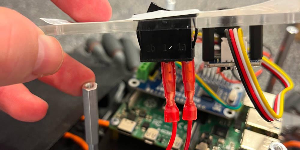
Tightly press the switch wires into the switch connectors. Make sure the connectors are flush with the switch.
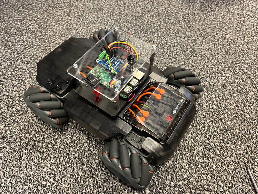
The finished assembly should look like this.