Hardware
Table of contents
Wire harness
| Component | Description | Quantity |
|---|---|---|
| Yellow wire AWG 24 45 cm | CAN L wire base to D131 | 1 |
| Green wire AWG 24 45 cm | CAN H wire base to D131 | 1 |
| Black wire AWG 20 30 cm | GND wire base to D131 | 1 |
| Red wire AWG 20 30 cm | 12V wire base to power switch | 1 |
| Black wire AWG 24 15 cm | GND wire D131 Jack to D131 CAN | 1 |
| Red wire AWG 24 15 cm | 12 wire power switch to D131 jack | 1 |
| Quick connect | Quick connect crimp for power switch | 2 |
| 2x2 ATX crimp housing | D131 power jack crimp housing | 1 |
| ATX crimp contacts | D131 power jack crimp contacts | 2 |
| AWG 24 Ferrules | CAN Ferrules | 3 |
| Harwin 2x2 crimp housing | For CAN base | 1 |
| Harwin crimp contacts | For CAN base | 4 |
| Tool | Description |
|---|---|
| Diagonal pliers | To cut the cable |
| Wire stripper | To isolate the wire strands |
| Crimping tool Harwin | Harwin wire crimper |
| Crimping tool ATX | ATX-style wire crimper |
| Crimping tool Ferrules | Ferrule crimper |
| Crimping tool quick connect | Quick connect crimper |
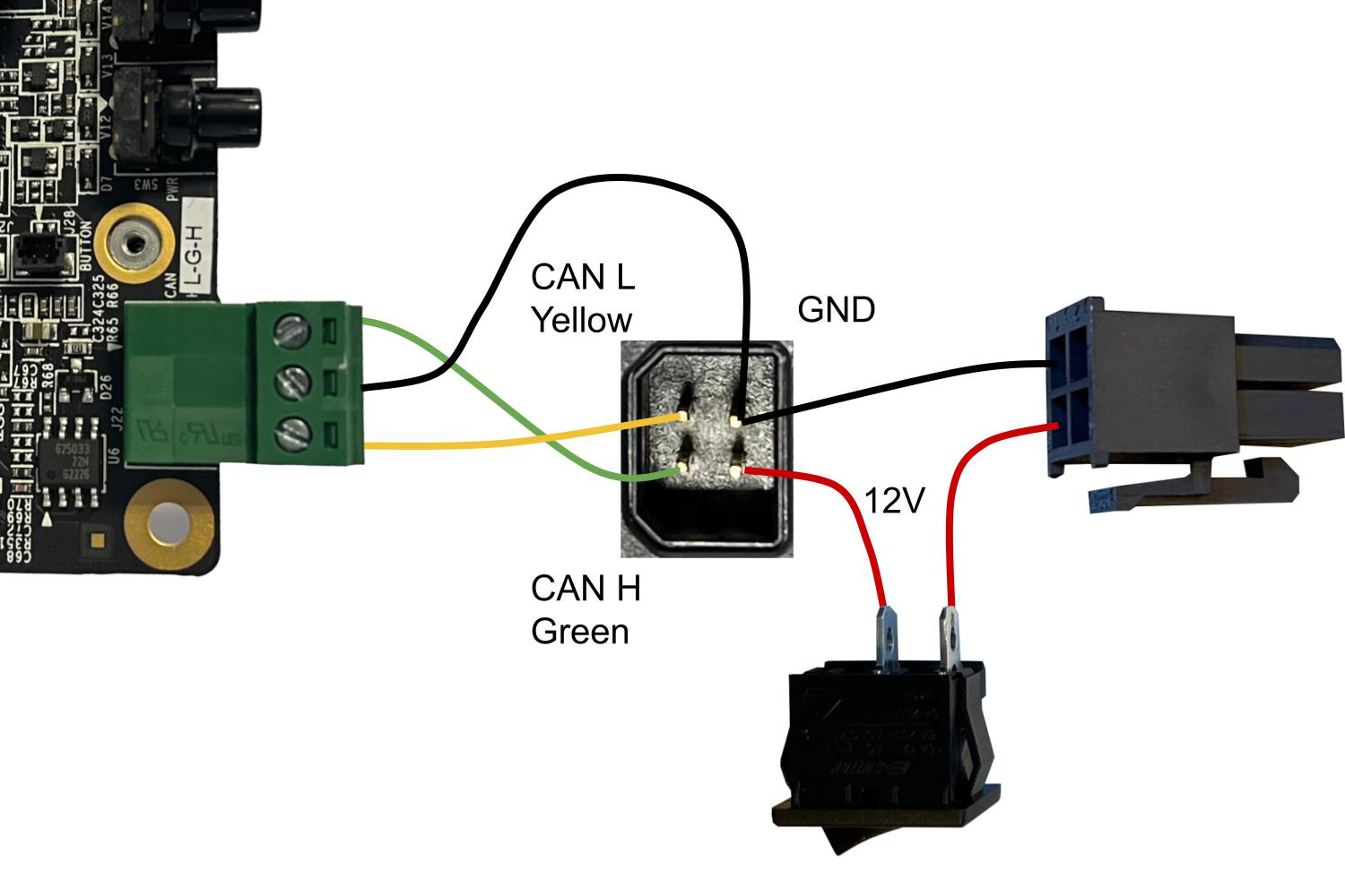
In the configuration with the Jetson Orin, the 12V is directly fed to the D131 carrier, interruptible with a power switch.
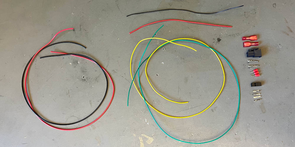
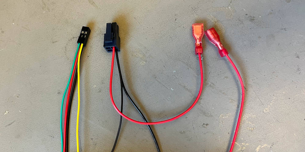
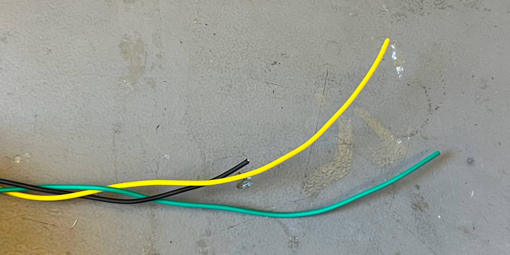
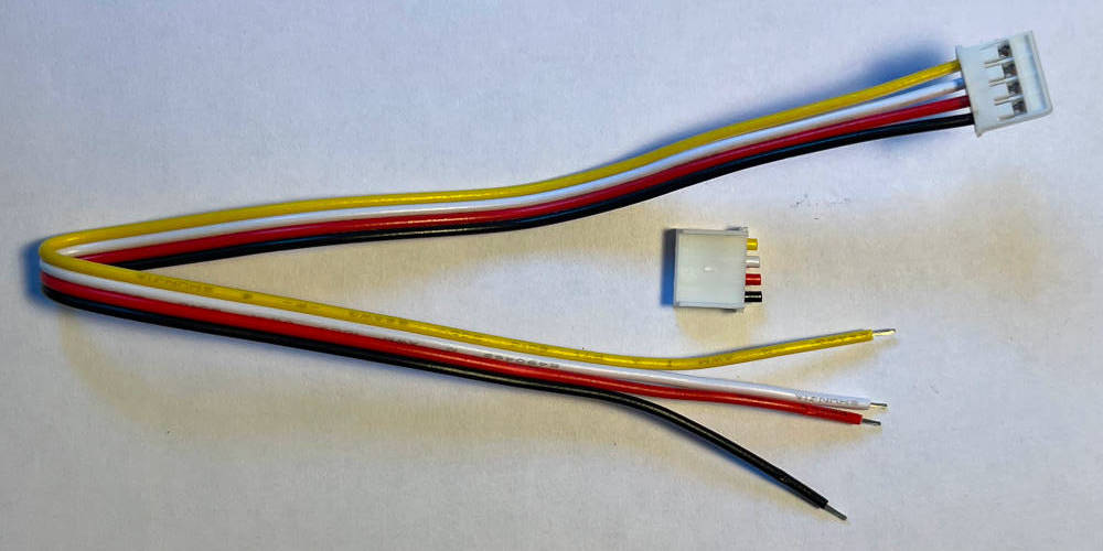
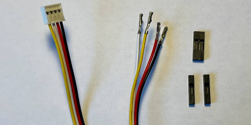
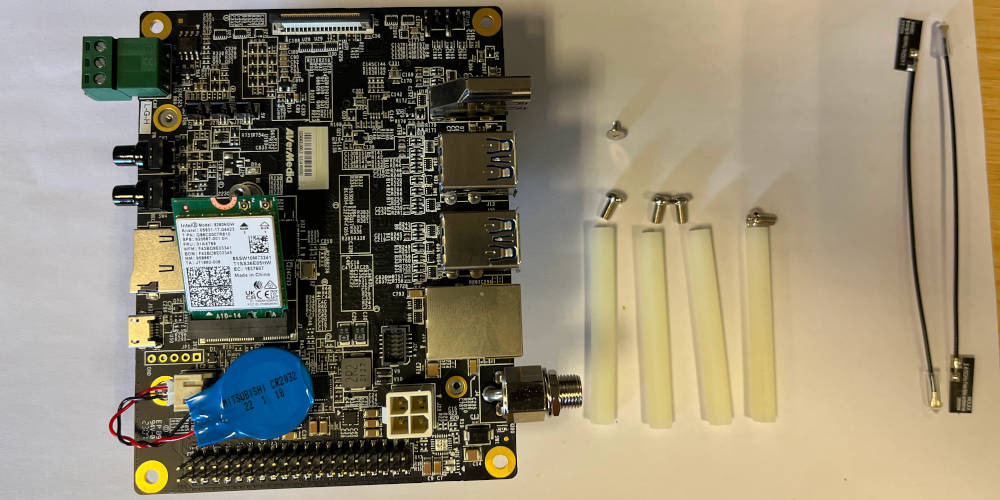
Overview of the wires and components used wire harness assembly.
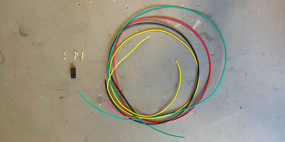
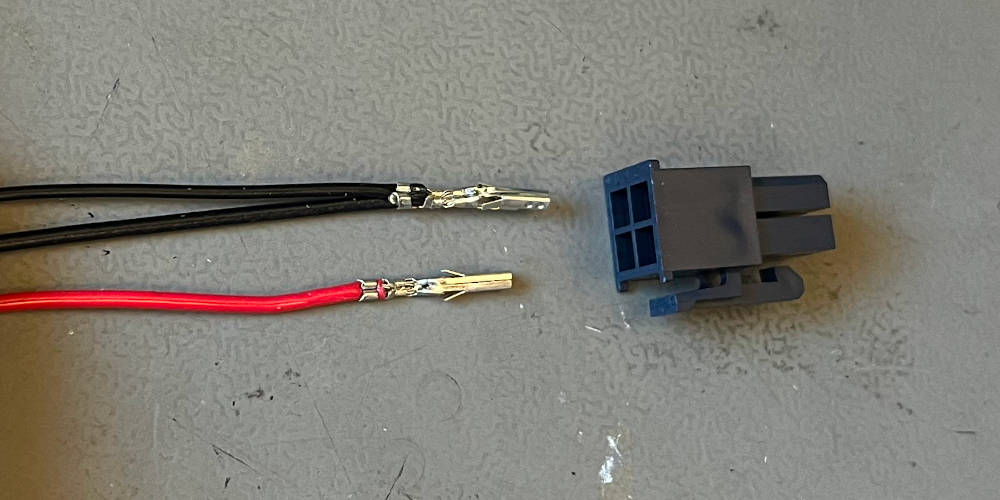
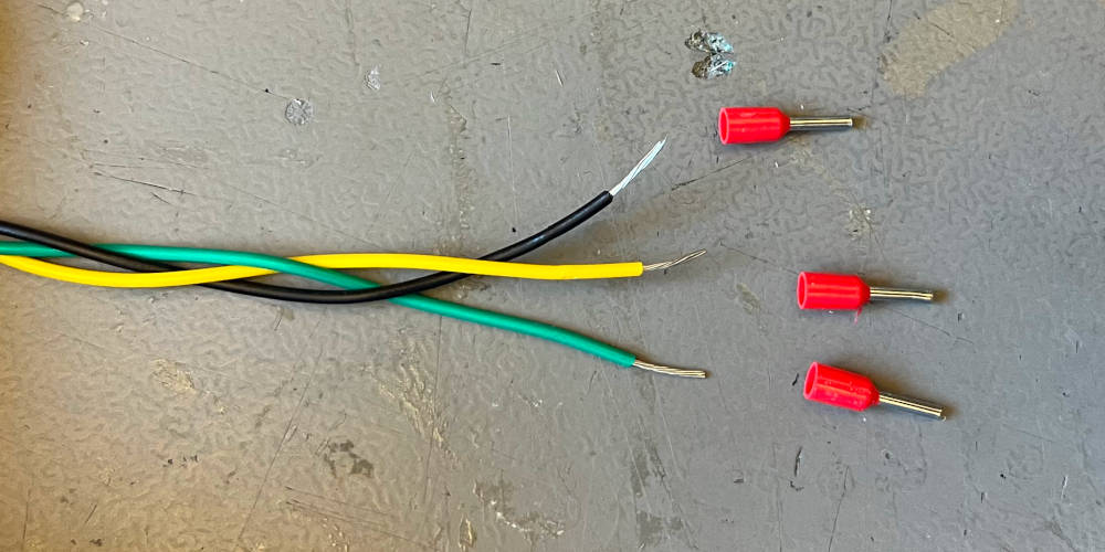
Start by finding the four long cables, four crimp connectors and the 2x2 crimp housing.
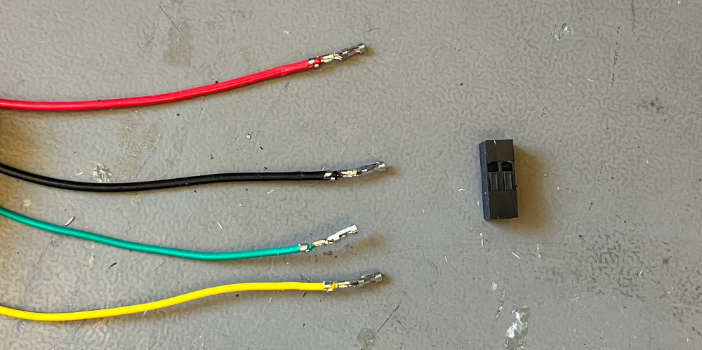
Remove the cable isolation on one end and crimp the four cables.
Insert the cables into the 2x2 housing. Start with the black cable at pin 1, indicated by the arrow. It is important to insert the cable with the correct orientation.
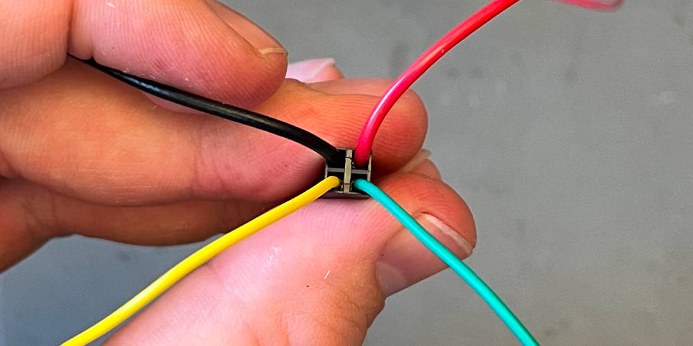
Insert the remaining cables.
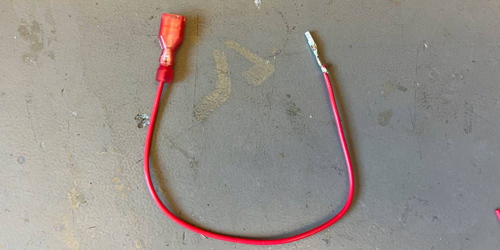
The short red cable is crimped to the D131 power jack on one side and to the power switch connector on the other side.
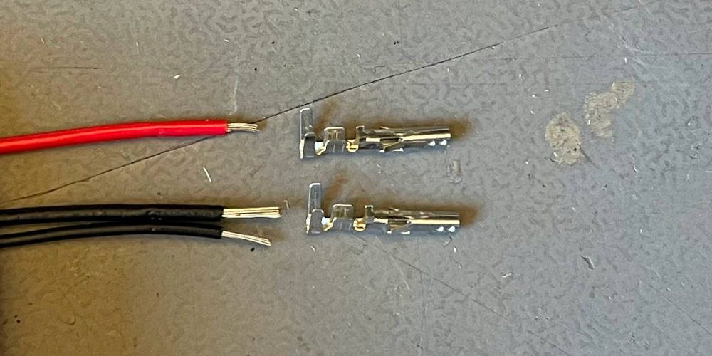
Find the power jack crimp contacts. Isolate the end of the short and long black cable.
Both black cables are crimped together into a single crimp contact connecting to the D131 power jack. Align the short positive and the two black crimped cables with the power jack housing and insert them in the bottom two holes.
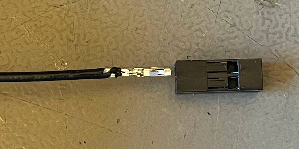
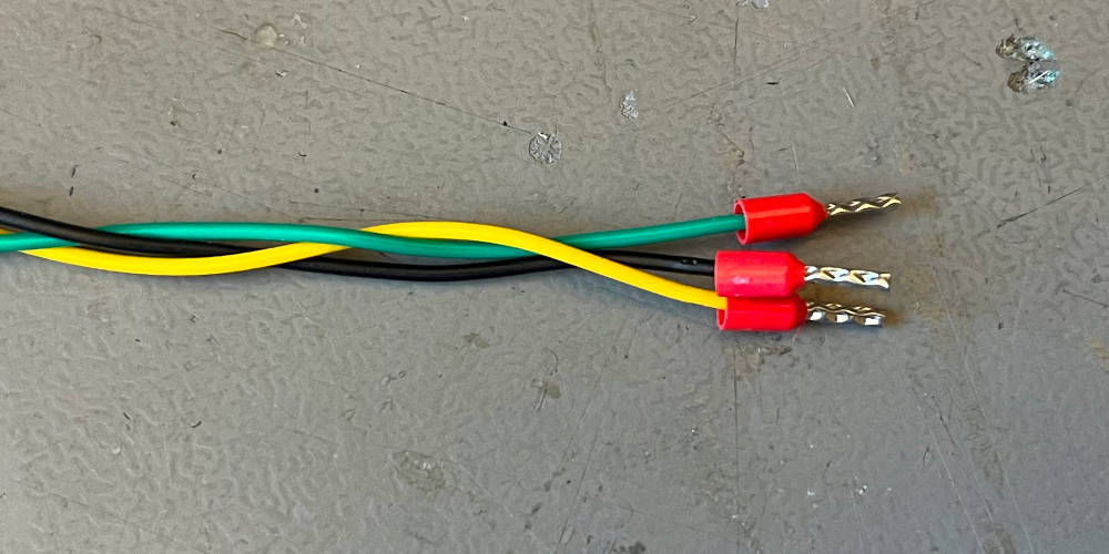
After crimping all wires, this is what the assembly looks like.
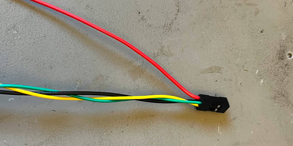
Weave the black, yellow and green cable together. Do not weave in the red cable.
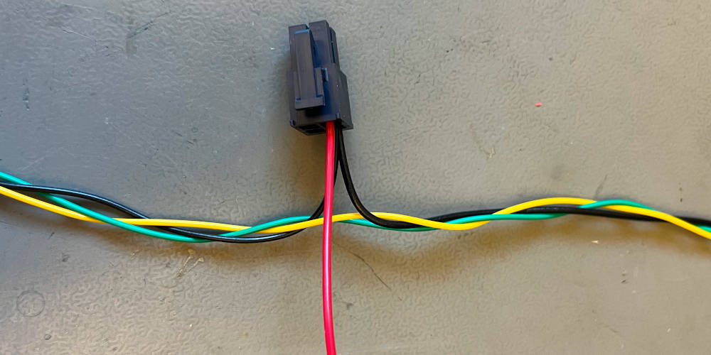
Continue the weaving towards the power jack, incorporating the short black wire.
Weave the black, yellow and green cable together towards the end.
Cut the wires to a similar length, isolate the ends and find the ferrules.
Crimp the ferrules to the three wires.
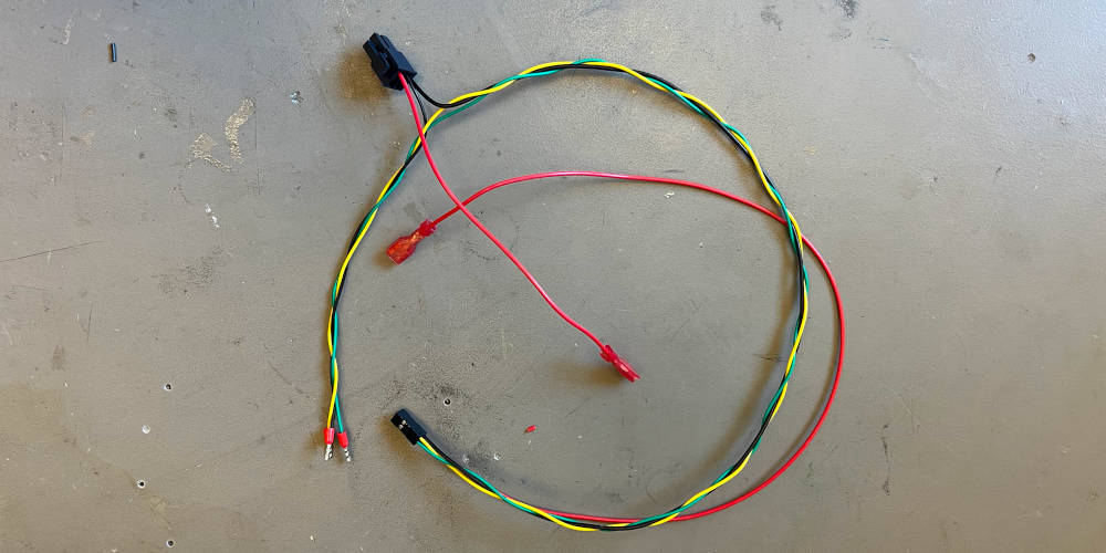
The wire harness is completed.
Robot
| Component | Description | Quantity |
|---|---|---|
| DJI RoboMaster S1 | Fully assembled and tested robot | 1 |
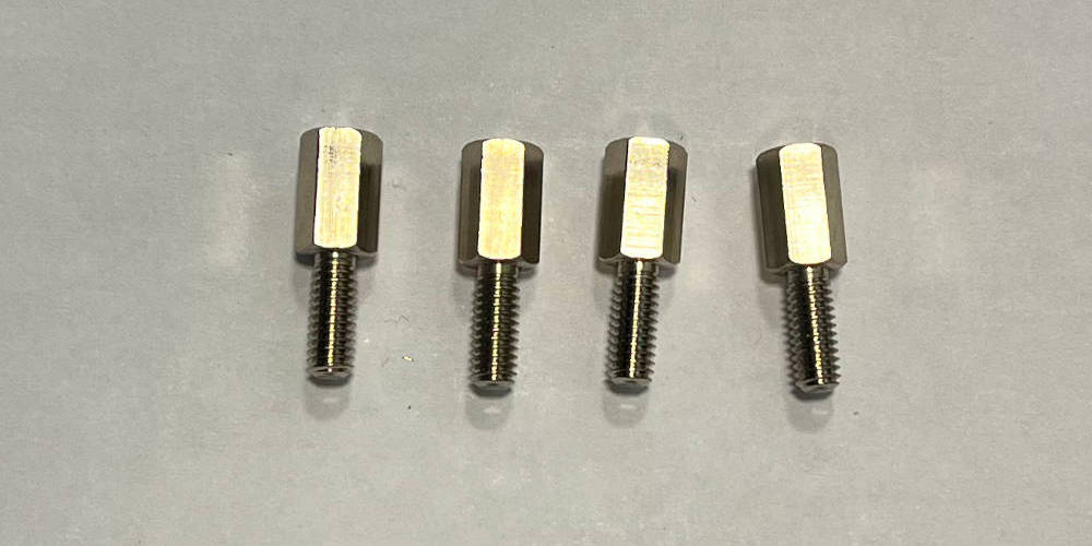
| M4 distance bolts 10mm | Distance bolts for base plate | 1 |
| Wire harness | Previously assembled wire harness | 1 |
| Tool | Description |
|---|---|
| Torx screwdriver | For the turret screws |
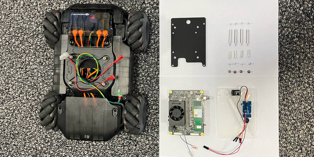
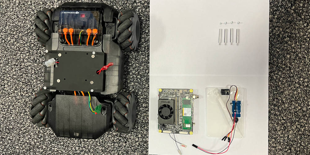
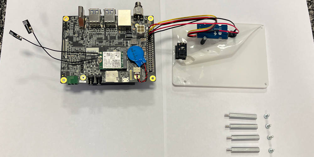
Overview of components needed.
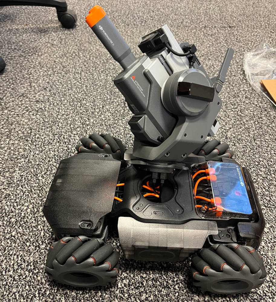
Unscrew the four turret screws and set them aside.
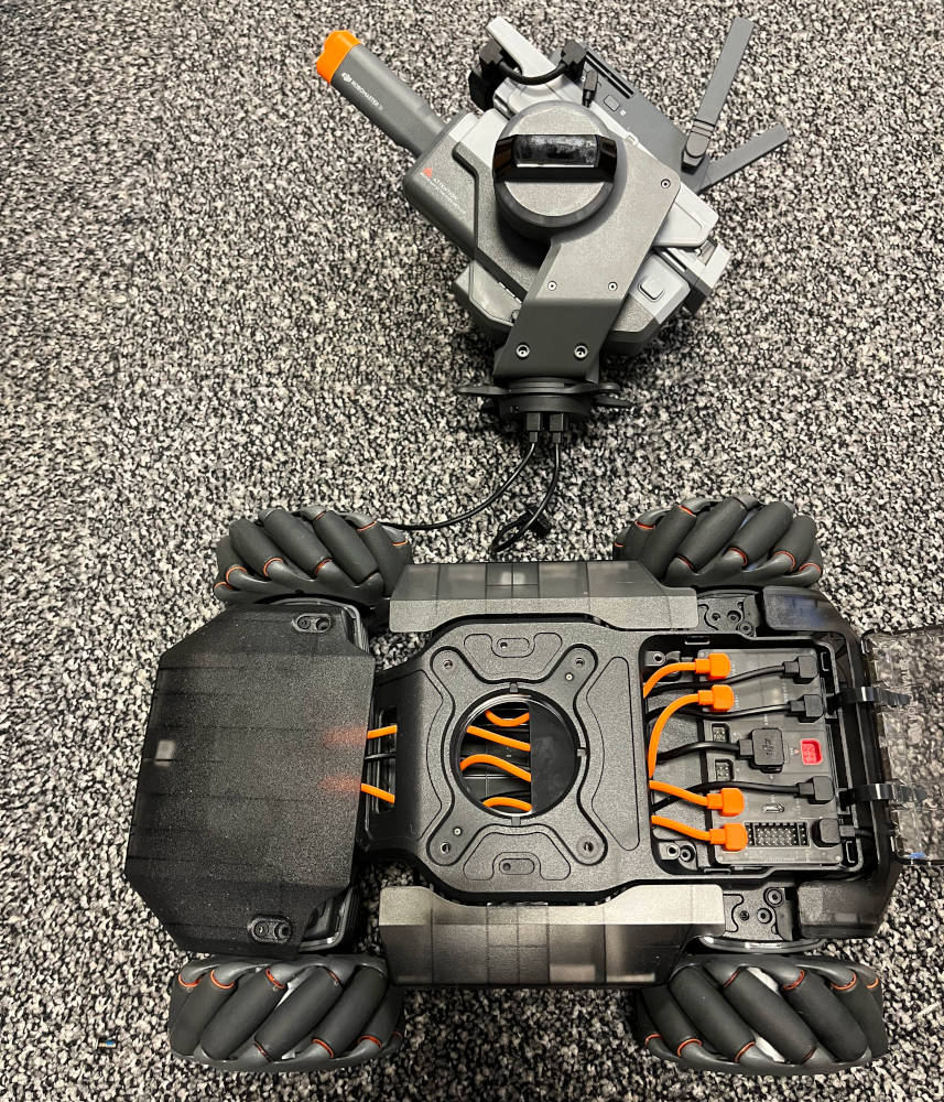
Remove the turret by disconnecting its two cables from the controller.
Screw in the four standoffs in place of the turret.
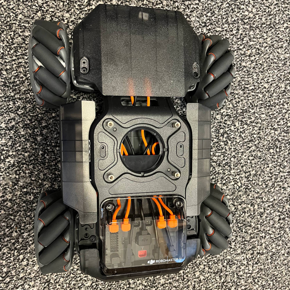
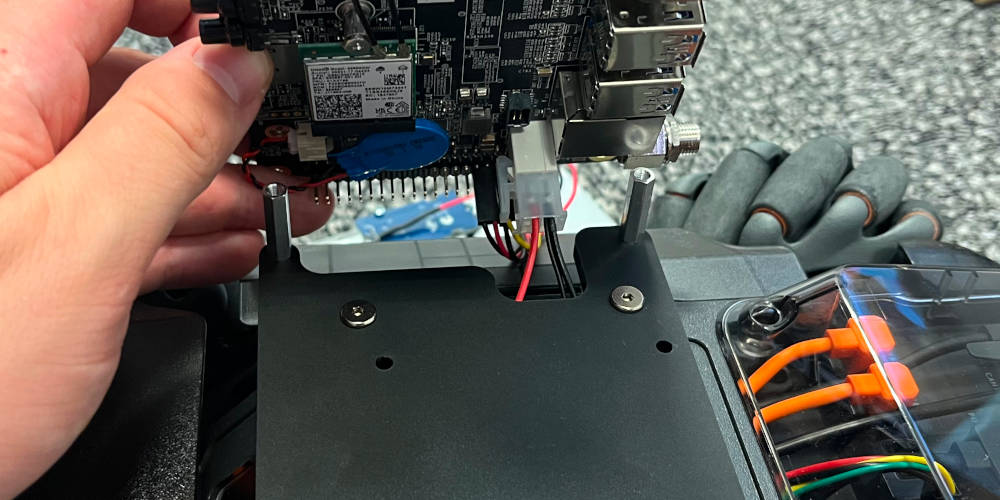
Take the assembled wire harness and thread through the 2x2 connector through the base to the controller.
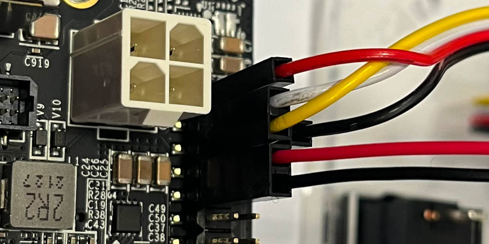
Connect the wires to the controller. It is essential that the wire is plugged in correctly, with black and red facing towards the center of the robot. It is possible to plug in the wires four ways, and plugging them in wrong will break the computer.
Overview of the base, with four standoffs and wire harness mounted.
UI Unit Cable
First, we assemble the I2C connection cable. Then, we assemble the rest of the UI unit.
| Component | Description | Quantity |
|---|---|---|
| OLED display Cable | I2C cable coming with the display unit | 1 |
| Harwin 2x1 | Crimp housing | 1 |
| Harwin 1x1 | Crimp housing | 2 |
| Harwin crimp contacts | Crimp contacts | 4 |
| Tool | Description |
|---|---|
| Diagonal pliers | To cut the cable |
| Wire stripper | To isolate the wire strands |
| Crimping tool | Harwin wire crimper |

Find the cable supplied with the display unit.
Cut off one end of the connector and prepare the cut off end of the cable for crimping.
Crimp all four wires and find the crimp housing (1x 2, 2x 1).
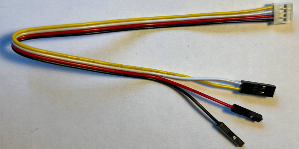
Connect the white and yellow cable to the 2x housing, and the black and red cable to the 1x housing.
UI Unit
| Component | Description | Quantity |
|---|---|---|
| UI front plate | Lasercut front plate | 1 |
| Power switch | Power switch | 1 |
| UI Button | Button to interact with UI | 1 |
| OLED display | UI display | 1 |
| Red wire 20cm | Signal wire for UI button | 1 |
| Red wire 4cm | Wire for pullup | 1 |
| Black wire 20cm | Gnd wire for UI button | 1 |
| Shrink tubing 2cm | Schrink tubing for wires | 3 |
| Resistor 1k5 | Pullup resistor for UI button | 1 |
| Harwin 2x1 | Crimp housing for UI button | 1 |
| Harwin crimp contacts | Crimp contacts | 2 |
| M2 distance bolt | Distance bolt to mount UI display | 2 |
| M2 screws 10mm | screws to mount display on bolts | 4 |
| Tool | Description |
|---|---|
| Diagonal pliers | To cut the cable |
| Wire stripper | To isolate the wire strands |
| Crimping tool | Harwin wire crimper |
| Phillips screwdriver | For small M2 screws |
| Soldering Iron | To solder wires |
| Heat gun | To apply shrink tubing to wires |
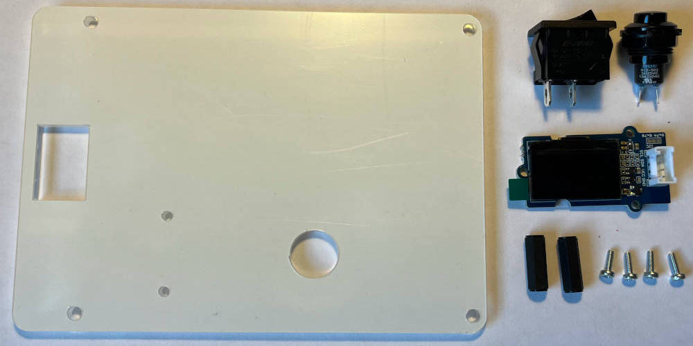
Overview of the parts used in the UI assembly.
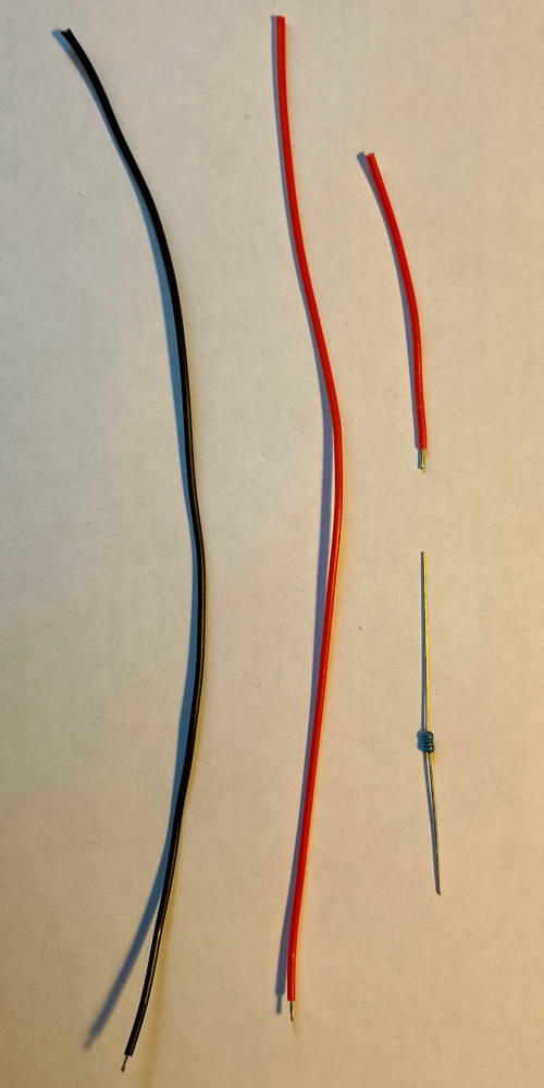
Overview of the wires used in the UI assembly.
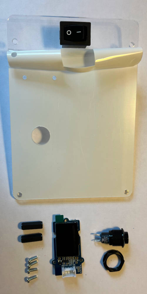
Align the front plate so that the rectangular hole is on the left, and the circular hole is on the bottom. Align the switch so that the off-position is on the bottom. Remove protective screen around the switch if necessary. Press the switch into the rectangular hole. Re-attach protective screen on top of the switch (optional).
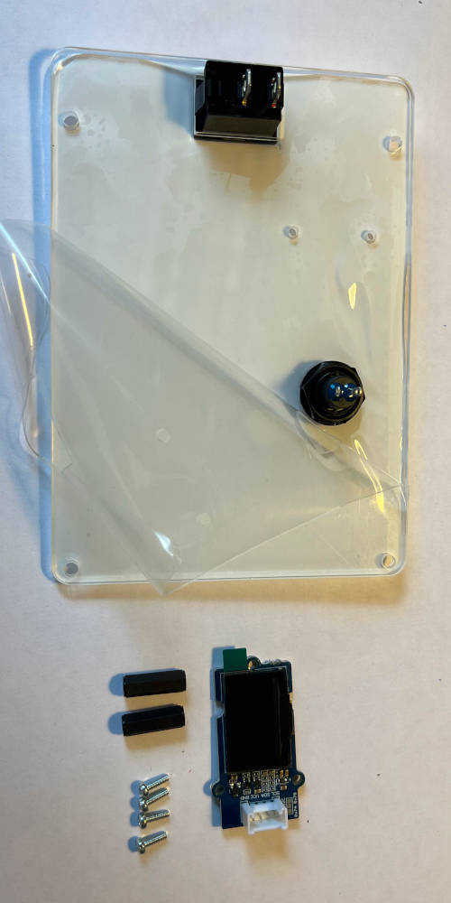
Turn the front plate on its back. Remove protective screen around the switch if necessary. Unscrew the nut from the button if not already done, and insert it through the front. Then screw the nut back on.
Take two screws and two distance bolts. Remove protective screen around the screw holes if necessary. Mount the distance bolts as indicated with two screws.
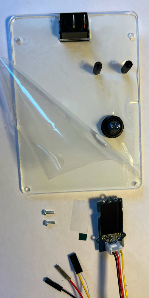
Attach the display cable to the display. Mount the display to the front plate on the standoffs.
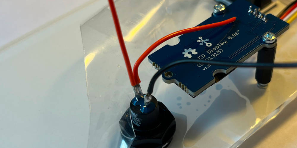
Take the wires and remove isolation from one side for soldering. Solder two colored wires to the top pin of the button so that the shorter wire is facing the display, and the longer wire facing upwards. Solder the black wire to the bottom pin.
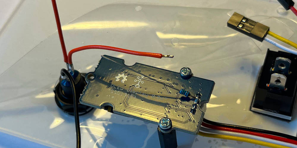
Take the pullup and cut one end to about 0.5cm length. Solder it to the second pin of the display (counted from top, pin corresponding to the red wire on the display). Cut the shorter cable of the button facing the display so that there is some overlap with the resistor, remove isolation and apply solder it.
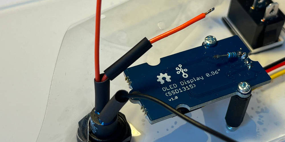
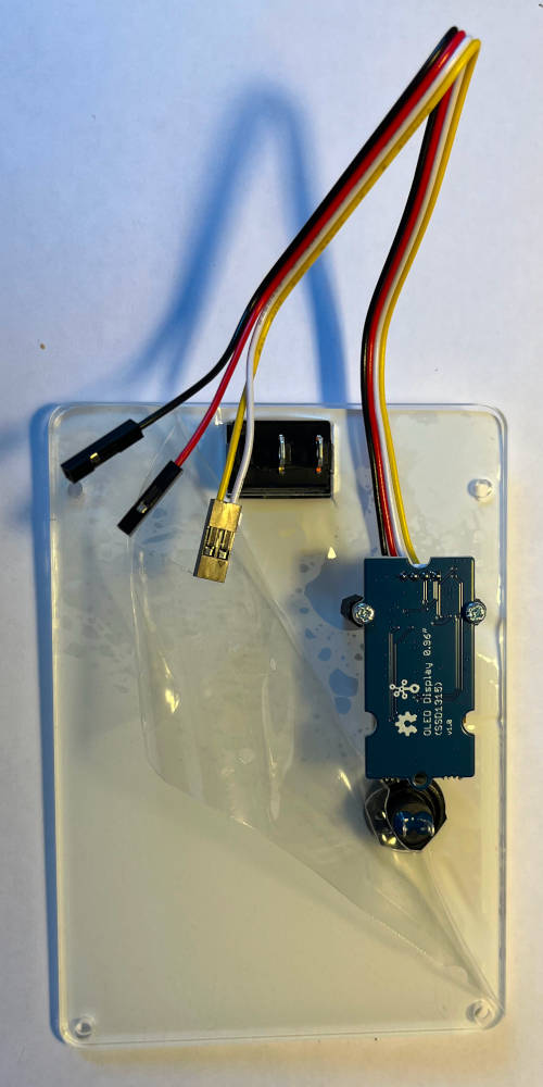
Cut three pieces of heat shrink and put them on both wires of the button and the resistor. Cut the resistor to the appropriate length so that the cable can be soldered on it.
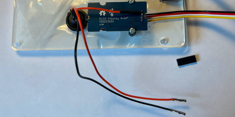
Apply heated air to all heat shrinks. Cut the wires of the button to a similar length and crimp the endings. Prepare a 2x housing.
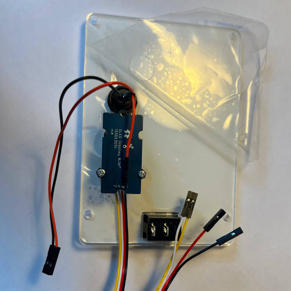
Insert the button wires into the housing.
Computer
| Component | Description | Quantity |
|---|---|---|
| D131 Carrier board box | Box containing the carrier board and mounting material | 1 |
| Jetson heat sink | Heat sink and fan unit for the Jetson Orin | 1 |
| Jetson Orin NX | Jetson Orin NX computer | 1 |
| WiFi module | Intel M2 WiFi module | 1 |
| WiFi Antenna | WiFi antenna for Intel module | 2 |
| SSD | SSD M2 256 GB | 1 |
| Tool | Description |
|---|---|
| Torx T6 | To screw in the Jetson mounting screws |
| Small Phillips | To unscrew fan |
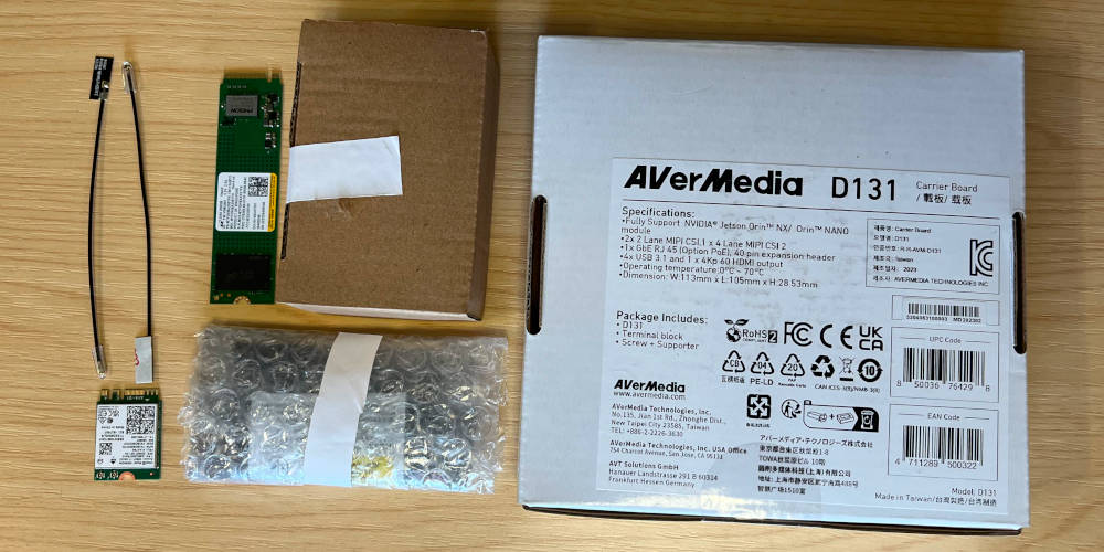
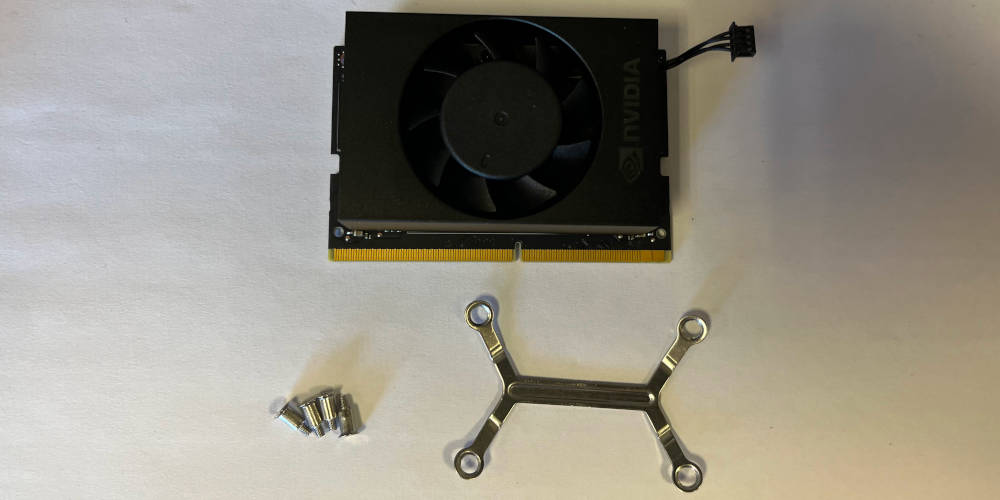
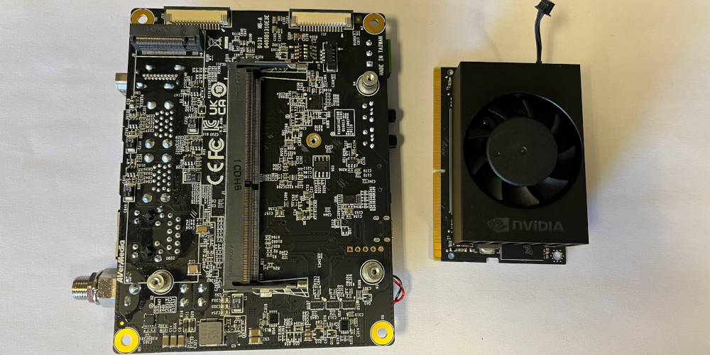
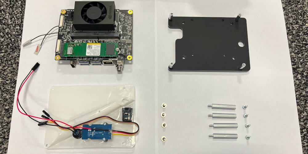
Find the Jetson Orin, the heatsink and the D131 carrier.
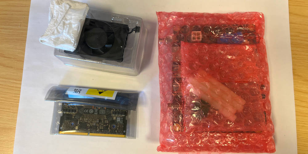
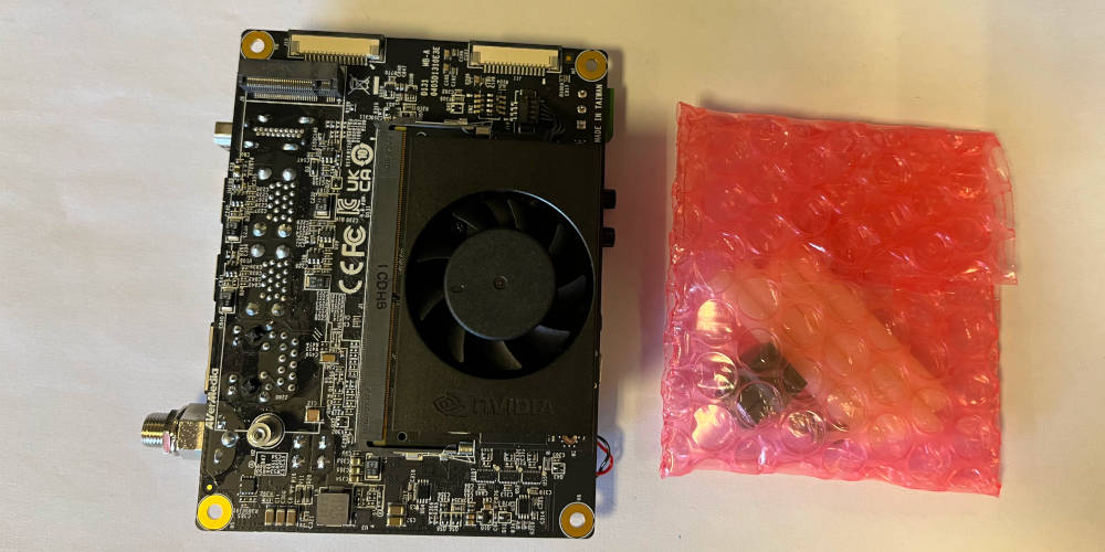
Unbox all items. The heatsink and the D131 carrier comes with a set of mounting components.
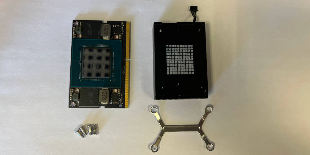
Unwrap the Jetson Orin and place the heatsink next to it, on its back. Note that the heatsink comes with pre-applied heat paste that must not be wiped. Place the four mounting screws and the mounting bracket next to the heatsink.
Place the heatsink on the Jetson Orin. Make sure to align it properly, with the groves in the heatsink matching the components on the Jetson Orin. Gently press the heatsink down to make sure it is properly seated.
Turn the heatsink with Jetson Orin around and place the mounting bracket on top of the heatsink. Make sure to align the bracket with the holes in the heatsink. The bracket is supposed to stand up, as shown, serving as a spring after screwing in.
Put down two screws diagonally first. This will make it easier to align the bracket with the heatsink. Then use the remaining two screws to secure the bracket.
The heatsink is now secured to the Jetson Orin with all four screws. The bracket should be flush with the heatsink.
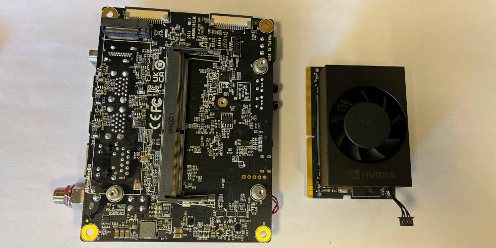
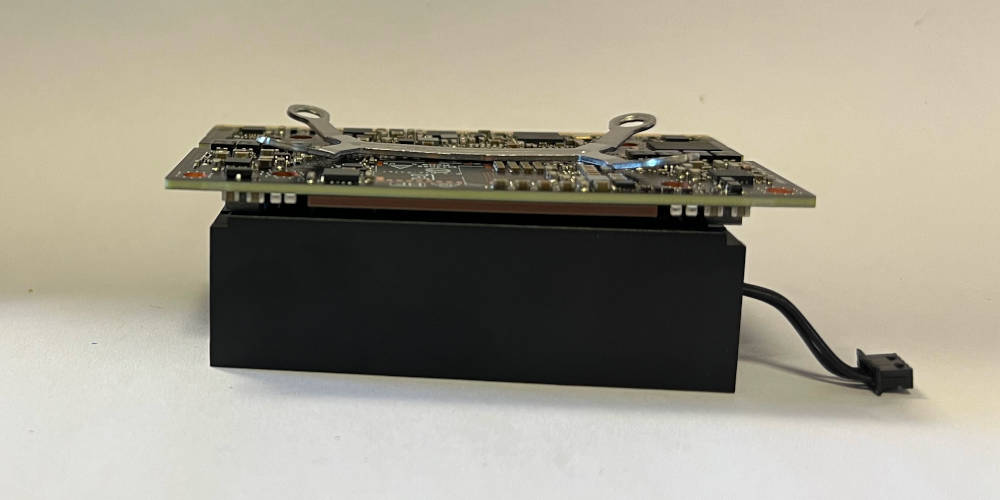
Plase the Jetson Orin next to the D131. Notice how the fan wire is facing to the bottom, but the fan connector on the D131 is on the top side.
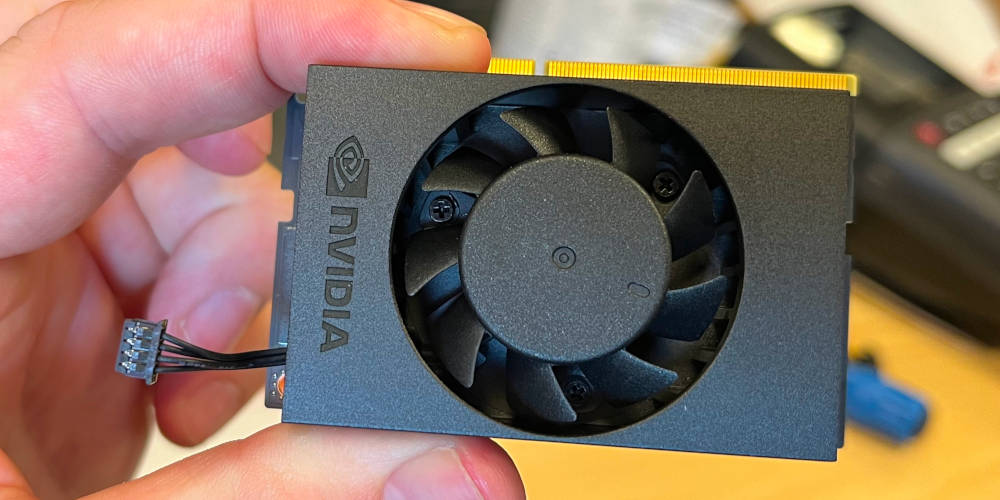
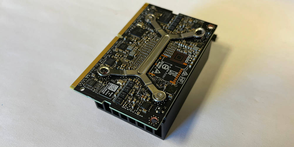
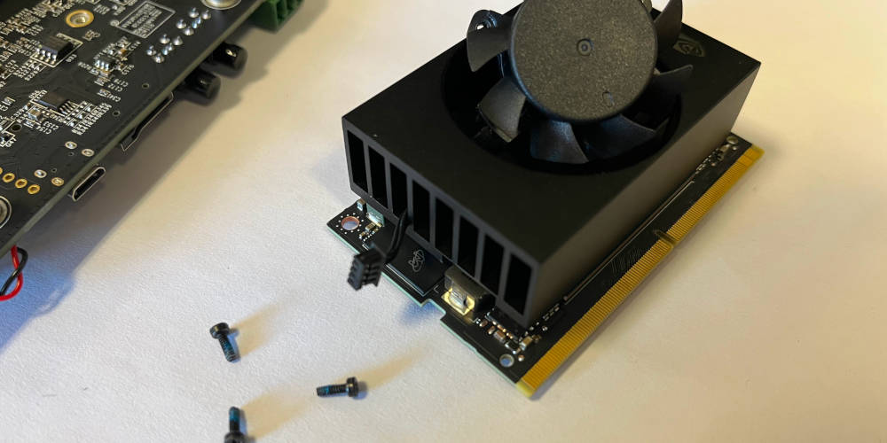
Pick up the Jetson Orin and localize the three screws mounting the fan.
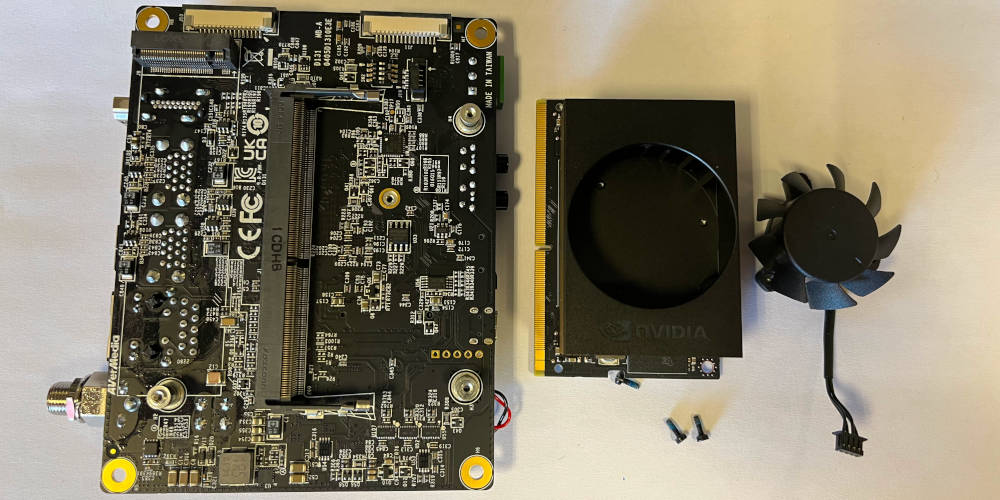
Unscrew the three screws holding the fan in place. Fully remove the fan from the heatsink.
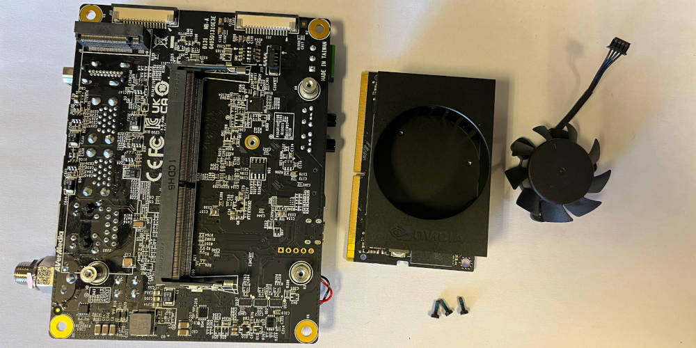
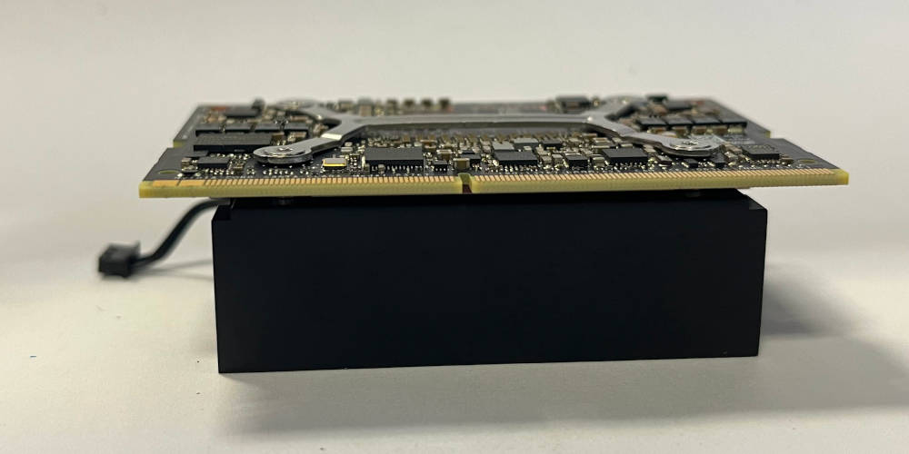
Rotate the fan 180 degrees.
Put the fan back into the heatsink. Thread the wire through the third fin hole from the left, then place it fully back into the hole, aligning it with the three screw holes. No force is needed to align the fan, it should fall into place.
Screw the fan back into place with the three screws previously removed.
Place the Jetson Orin into the D131 carrier. Connect the fan wire to the connector on the D131. Find the bag with the mounting components delivered with the D131 carrier.
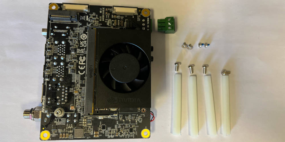
The bag should contain two kinds of two small screws each, four M3 screws, four plastic distance bolts and a green connector for the CAN bus.
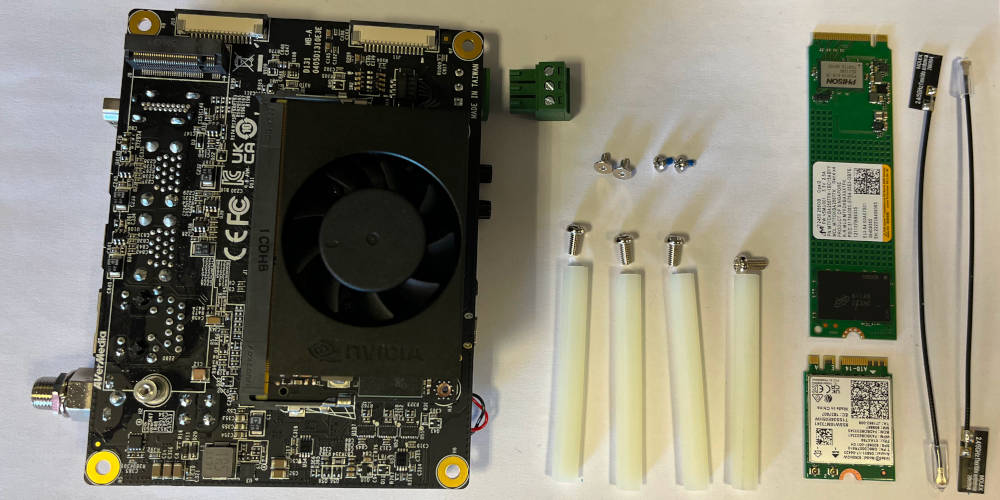
Find the SSD, the WiFi module and the antennas.
Find the two small screws with a rounded head, and screw the Jetson Orin in place. Place the CAN bus connector in the designated slot.
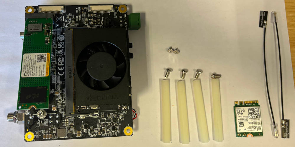
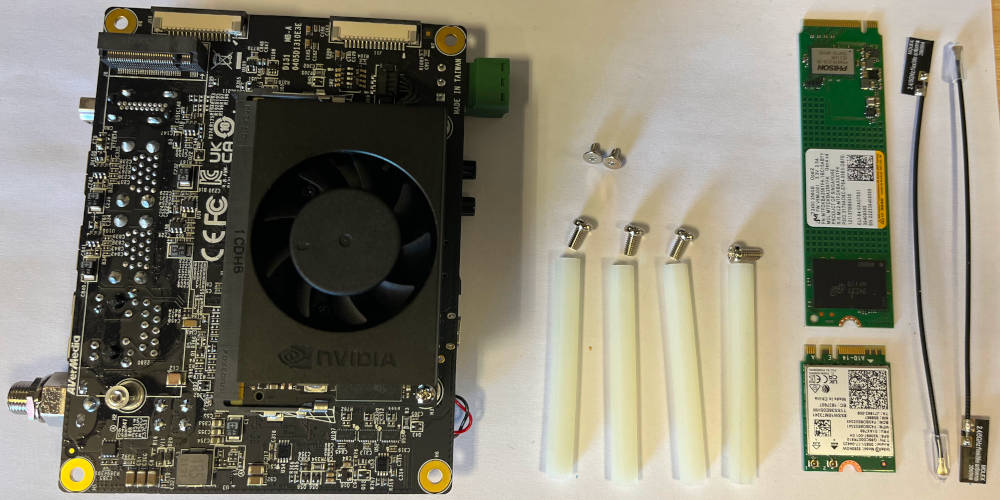
Place the SSD into the designated slot on the D131 carrier.
Screw in the SSD with one of the small screws with a flat head.
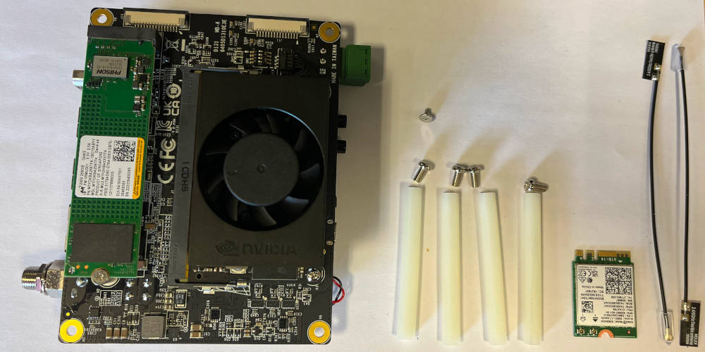
Turn the D131 carrier around and place the WiFi module into the designated slot.
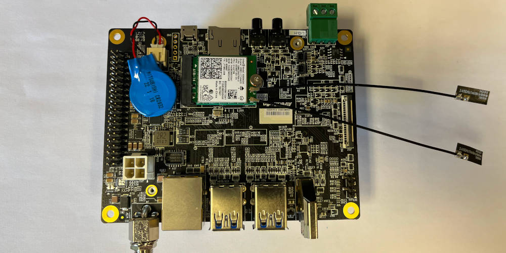
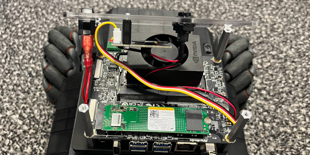
Screw in the WiFi module with the remaining small screw with a flat head. Connect the antennas to the WiFi module. The compute unit is now fully assembled.
Robot
| Component | Description | Quantity |
|---|---|---|
| Compute unit | Assembled D131 carrier and Jetson | 1 |
| Base plate | Lasercut base plate | 1 |
| M3x17 F/F distance bolts | To mount the compute unit on the base plate | 4 |
| M3x35 M/F distance bolts | To mount the UI unit on the compute unit | 4 |
| M3x10 screws | Screws to mount distance bolts | 4 |
| M4 screws | Screws that originally held the turret in place | 4 |
| Tool | Description |
|---|---|
| Small slot screwdriver | To screw in the CAN wires into the CAN header |
| Torx screwdriver | Screwdriver coming with the RoboMaster, to mount the M4 screws |
| Pliers | To hold distance bolts in palce or mount the power switch connectors |
Overview of components used in the base assembly.
Mount the four 17mm bolts to the base plate, as indicated, using M3 screws to fixate them.
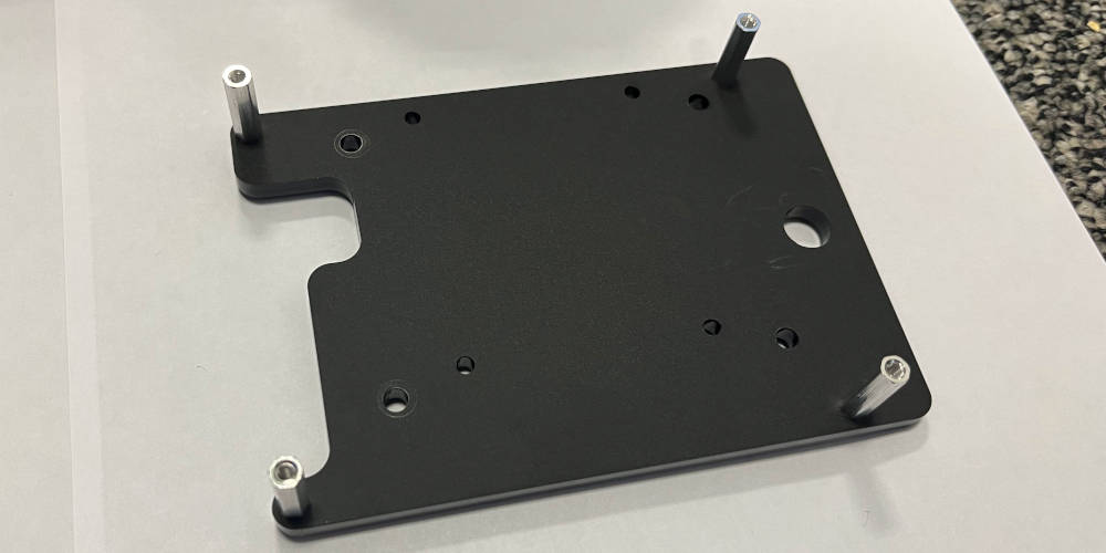
The four bolts are mounted to the four outermost mounting holes.
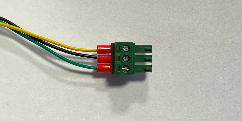
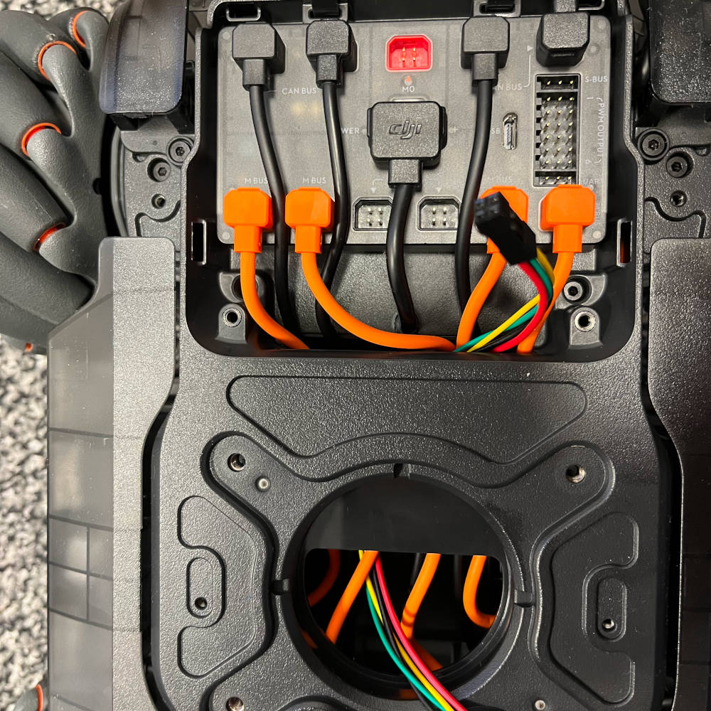
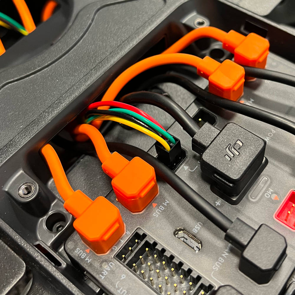
Screw in the ferrules of the CAN wires to the CAN header of the D131 carrier.
Organize the wire harness so that the two red wires are between the two topmost distance bolts, the power supply are between the opposite distance bolts and the CAN connector between the two right distance bolts. If the cables are too long, tuck them into the hole of the base unit as appropriate. Thread through the two red wires through the hole on the top of the base plate. Align the D131 power jack connector so that it fits into the cutout on the other end of the base plate. Screw in the base plate with the four M4 screws originally used to mount the turret on the RoboMaster.
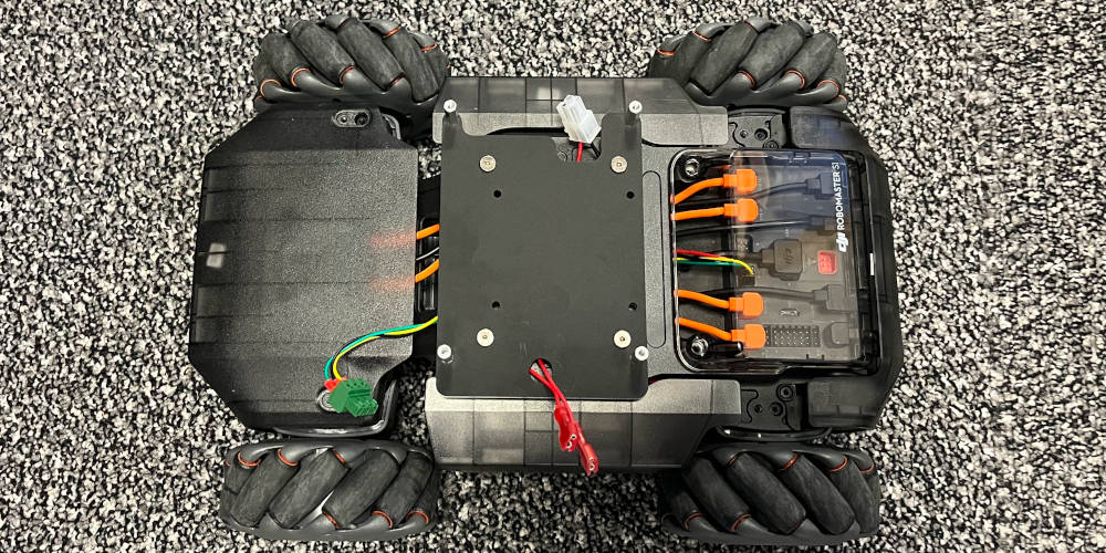
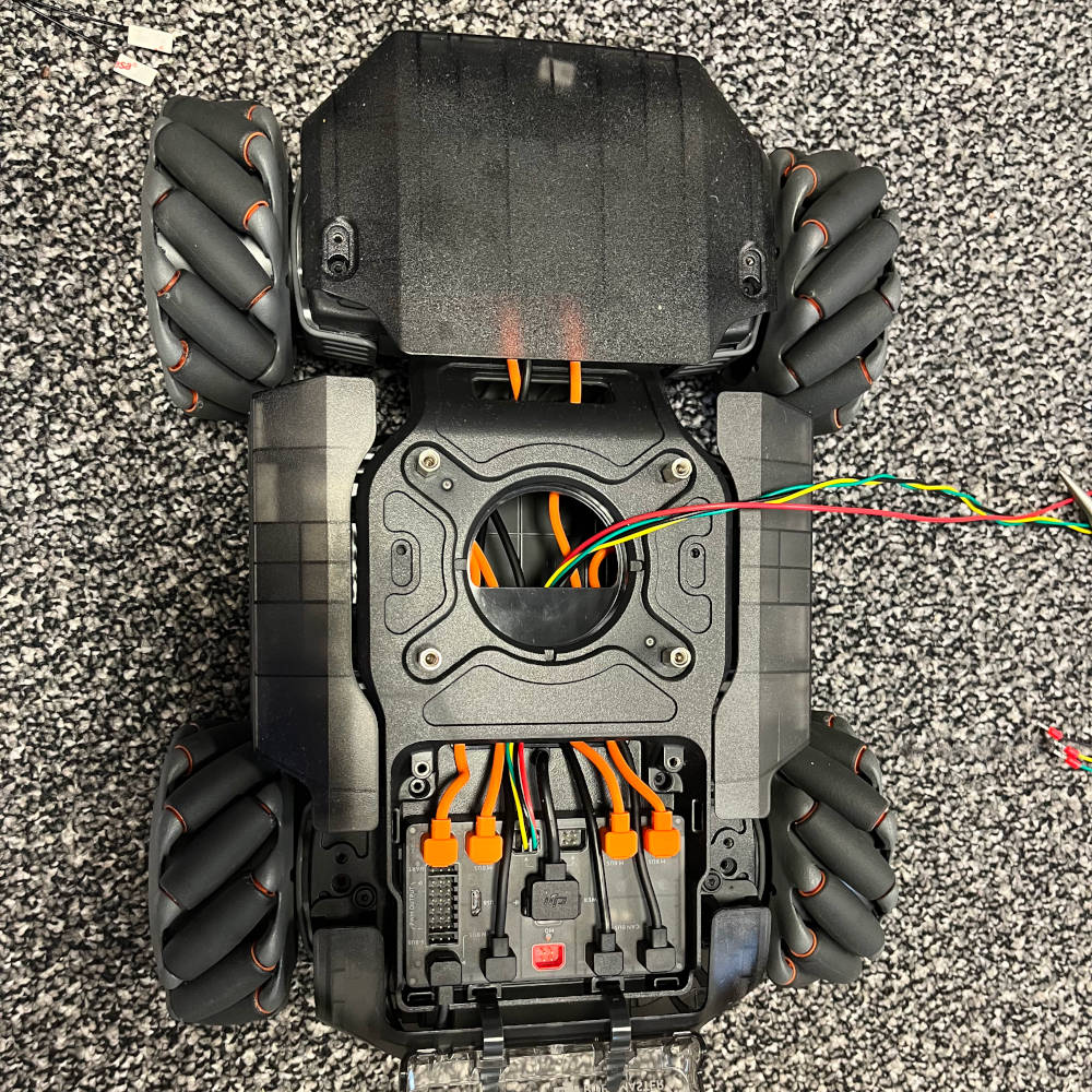
Close up of the mounted base plate.
Connect the UI assembly to the D131 carrier board.
Connected UI assembly.
Connect the power supply to the D131 carrier first, as indicated.
Flip down the carrier board and align the mounting holes with the four 17mm bolts. Fixate the carrier board with four 35mm bolts. Connect the CAN connector to the D131 carrier.
Connect the quick connector to the power switch. This may take some force to ensure a proper seat (they should reach all the way to the button). Route the wires coming from the UI assembly as indicated.
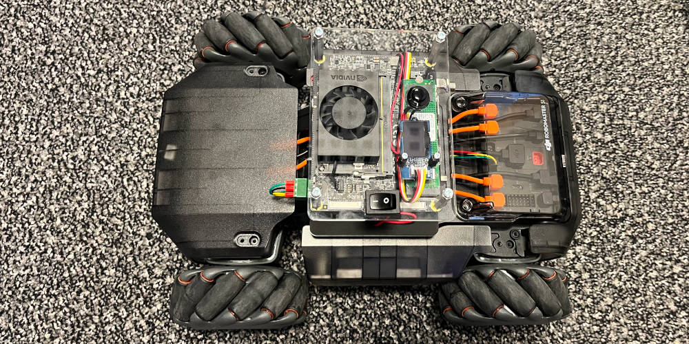
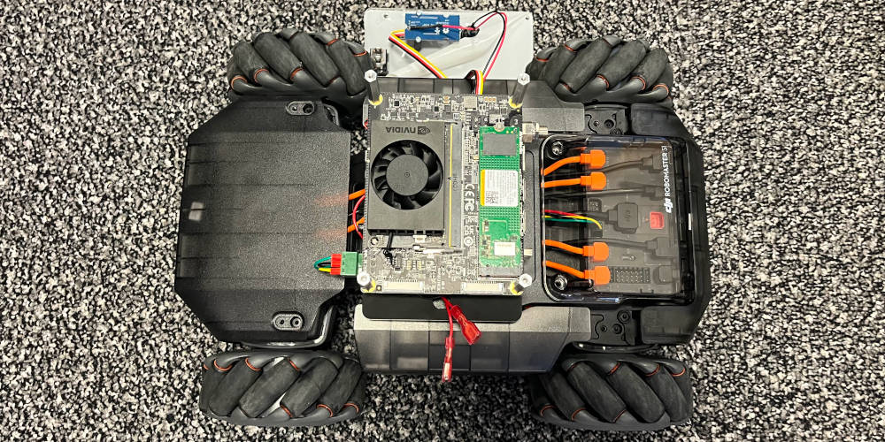
The robot is now fully assembled.